
Medical device extraction tool

a technology for extraction tools and medical devices, applied in the field of medical instruments, can solve the problems of patient injury, high cost, and complicated construction of state of the art known force-limiting devices

Inactive Publication Date: 2008-04-24
ALFRED E MANN FOUND FOR SCI RES
View PDF23 Cites 9 Cited by
  • Summary
  • Abstract
  • Description
  • Claims
  • Application Information

AI Technical Summary

Problems solved by technology

Frequent use of excess pressure on the remote tool parts can lead to material fatigue or even to the remote tool parts fracturing, whereupon loss of small parts in the operating arena, particularly during an operation can lead to the patient getting injured.
These state of the art known force-limiting devices are complicated in construction and are therefore expensive.

Method used


Image

  • Medical device extraction tool
  • Medical device extraction tool
  • Medical device extraction tool

Examples


Embodiment Construction

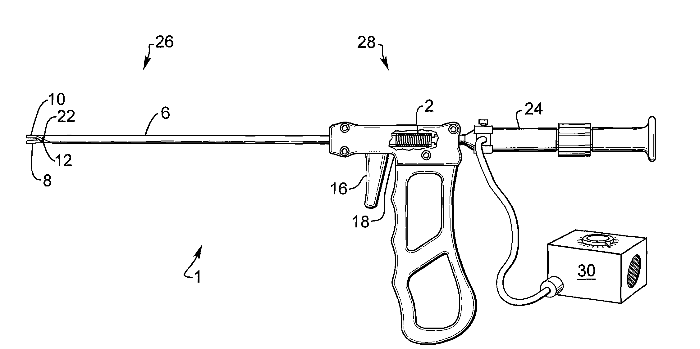
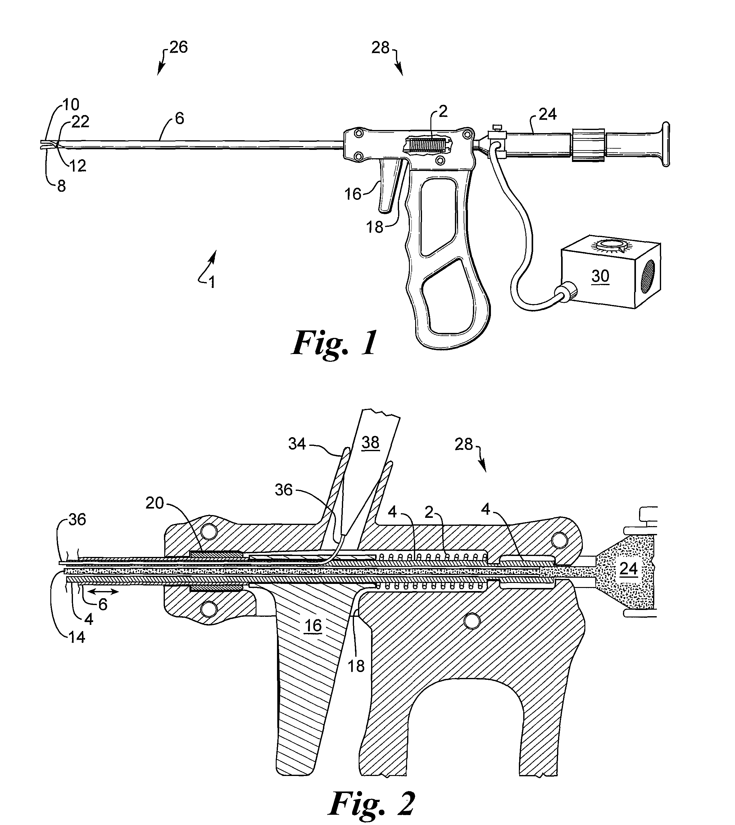
[0015]FIG. 1 depicts a medical surgical instrument in the form of a gripping tool 1. The gripping tool 1 has an activation tube 6 which is a hollow cylindrical shaft that extends along its lateral length. On the proximal end 28 of tube 6, a hand manipulator including activation trigger 16 and an optical imaging system 24 with a light source 30 are located.

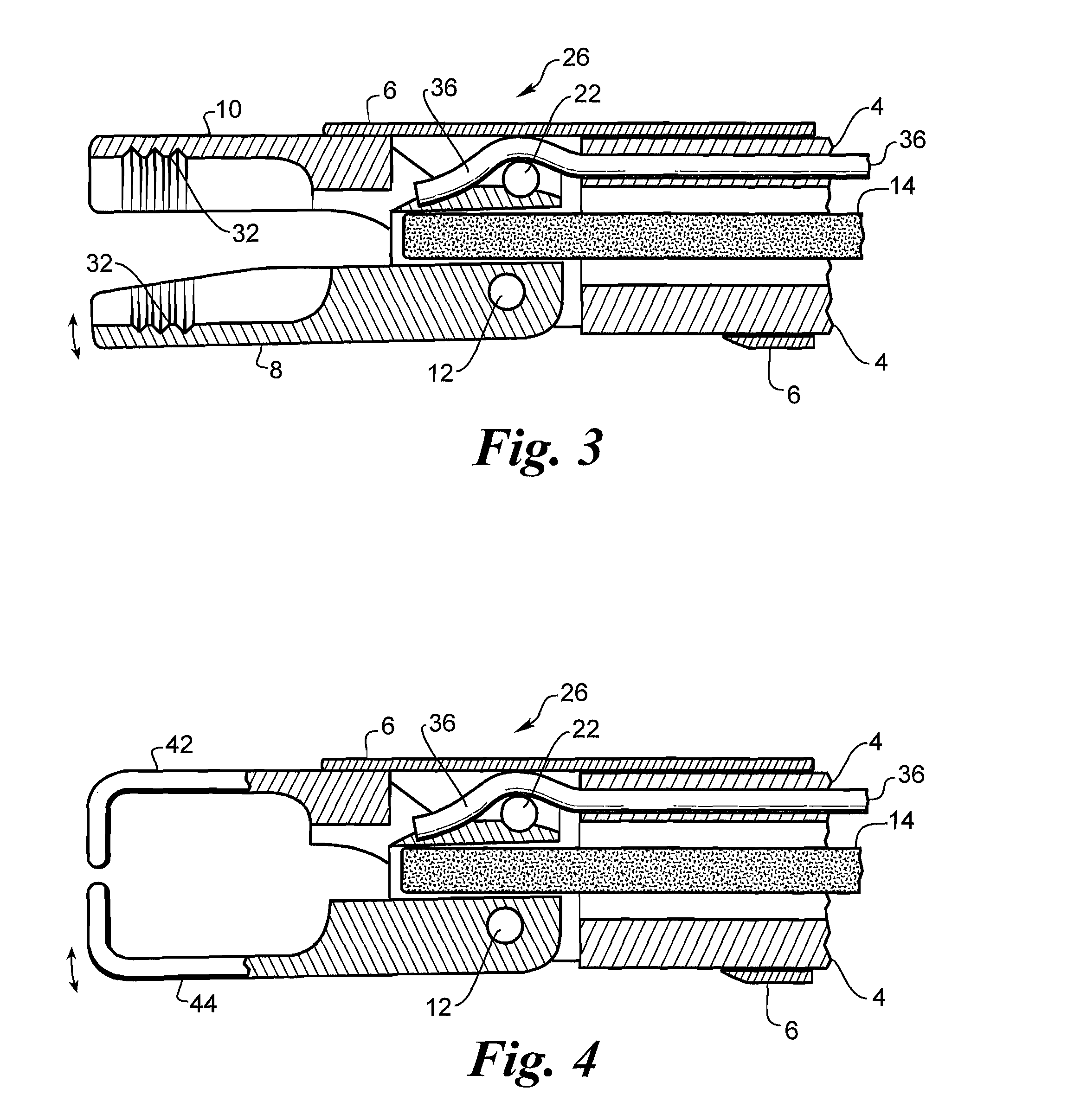
[0016]On the distal end 26 of the activation tube remote tool parts, for example jaws 8, 10 or hooks 42, 44 [FIG. 4], are arranged in the form of two open-ended sections which can be activated via the activation trigger 16 of the gripping tool 1. The trigger 16 moves the activation tube 6 along a line of displacement. The tool includes a fixed jaw 10 and a moveable jaw 8.

[0017]Because a hand can exert considerably greater force than 150 N, the gripping tool 1 depicted has a force-limiting spring 2. The force-limiting spring 2 is there to prevent undue excess force being exerted onto the jaws 8, 10 via the activation tube 6 which ca...


PUM


Abstract

A medical instrument, particularly a surgical instrument with a displaceable push / pull activation tube arranged on the proximal end of a hand manipulator, that also contains an inner tube for retaining a fixed jaw, for activating remote tool parts on the distal end, in which a force-limiting device limits the transmission of force to the remote tool parts from the hand manipulator via an extendable coil spring. The medical instrument optionally features a fiber scope to enable optical viewing to locate the implanted device for removal as well as a saline flush capability. The instrument has jaws that are cylindrical in shape to facilitate grasping an implanted cylindrical device.

Description

BACKGROUND OF THE INVENTION[0001]The invention relates to a medical instrument, particularly a surgical instrument with a displaceable push / pull rod arranged on the proximal end of a hand manipulator for activating remote tool parts on the distal end, wherein a force-limiting device is envisaged for limiting the transmission of force from the hand manipulator onto the remote tool parts via the push / pull rod.[0002]This kind of medical instrument can be a removal tool for microstimulators or microsensors, as well as a needle holder, a gripping, holding or preparation tool, scissors or other instrument, in which the push / pull rod can be moved back and forth using manual force via the hand manipulator, in order to move, i.e. to open and close, the remote tool parts which are predominantly open-ended tool parts.[0003]The specific microstimulators of interest to the instant application are small, approximately 6 mm diameter by 30 mm long cylinders, implantable electrical devices that pass...

Claims


Application Information

Patent Timeline
Patent Type & Authority Applications(United States)
IPC IPC(8): A61B17/00
CPCA61B2017/00796A61B17/0401
Inventor CALDERON, JOSEPH L.SCHULMAN, JOSEPH H.HILLERY, EDWARD
Owner ALFRED E MANN FOUND FOR SCI RES
Learn More