Axial Force Control Nut Assembly

a technology of axial force control and nut assembly, which is applied in the direction of fastening means, screws, load-modified fasteners, etc., can solve the problems of cracking of the disk wheel, insufficient fastening, and bolt breakage,

Inactive Publication Date: 2008-04-24
TOPY INDUSTRIES
View PDF3 Cites 6 Cited by
  • Summary
  • Abstract
  • Description
  • Claims
  • Application Information

AI Technical Summary

Benefits of technology

[0010] (b) which is easy to accurately determine whether or not a bolt axial force reaches a proper axial force (and does not reach an excessive axial force, though the determination of the excessive axial force may not necessarily be conducted).

Problems solved by technology

As a result, a bolt axial force corresponding to the torque may or may no be generated in the bolt, and an insufficient fastening may occur.
The insufficient fastening may cause a crack in the part (disk wheel) and breakage of the bolt.
Fastening using excessive fastening torque may cause breakage of the bolt.
Further, due to the friction of the contact surface, surface roughing and abrasion of the nut seat surface of the wheel may initiate a crack of the wheel.
However, since the deformation amount of the elastic member is continuous and small, the examination requires skill and it is difficult to find a point where an increasing bolt axial force just reaches the proper bolt axial force.

Method used


Image

  • Axial Force Control Nut Assembly
  • Axial Force Control Nut Assembly
  • Axial Force Control Nut Assembly

Examples


embodiment 1

b> And 18

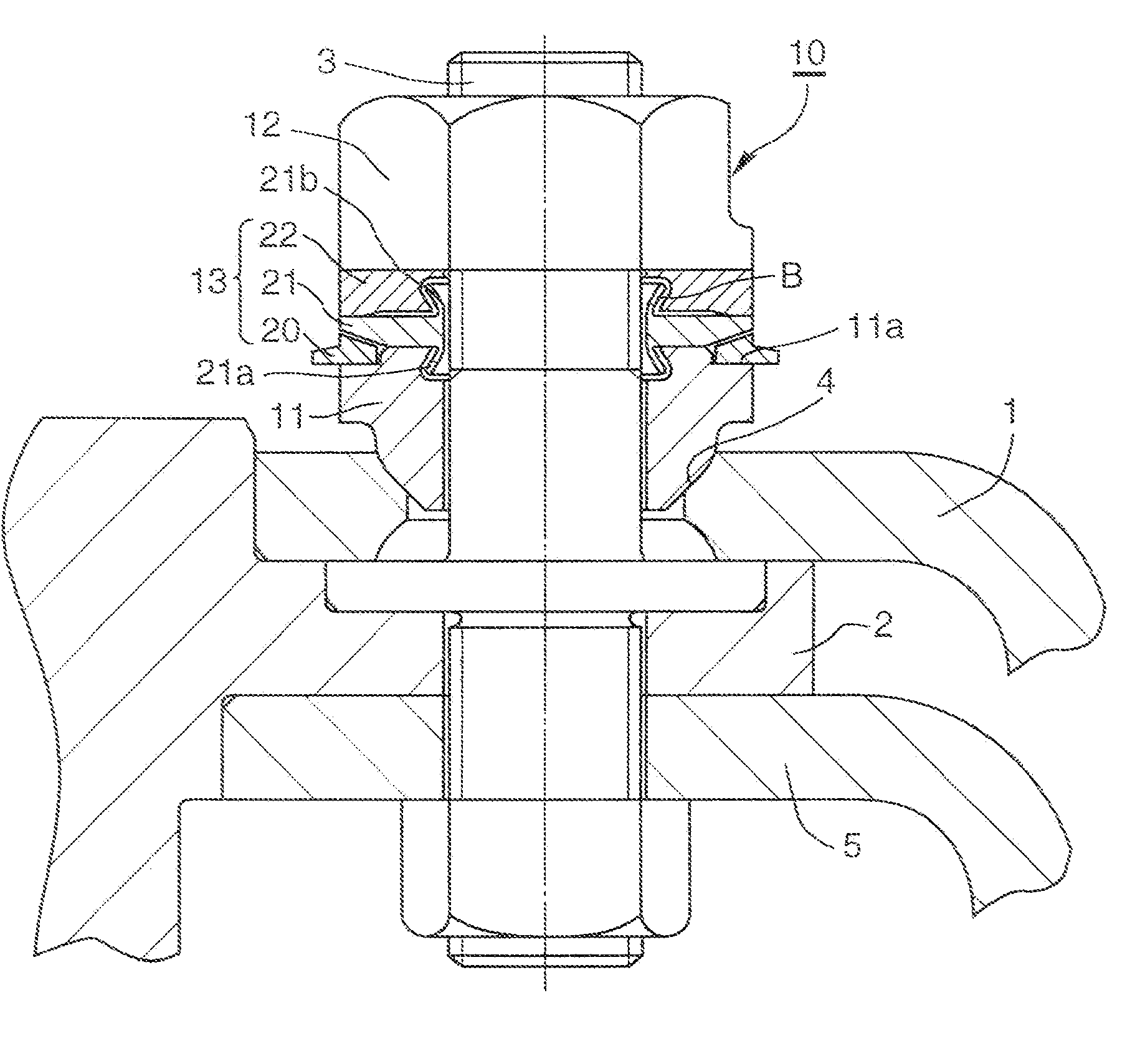
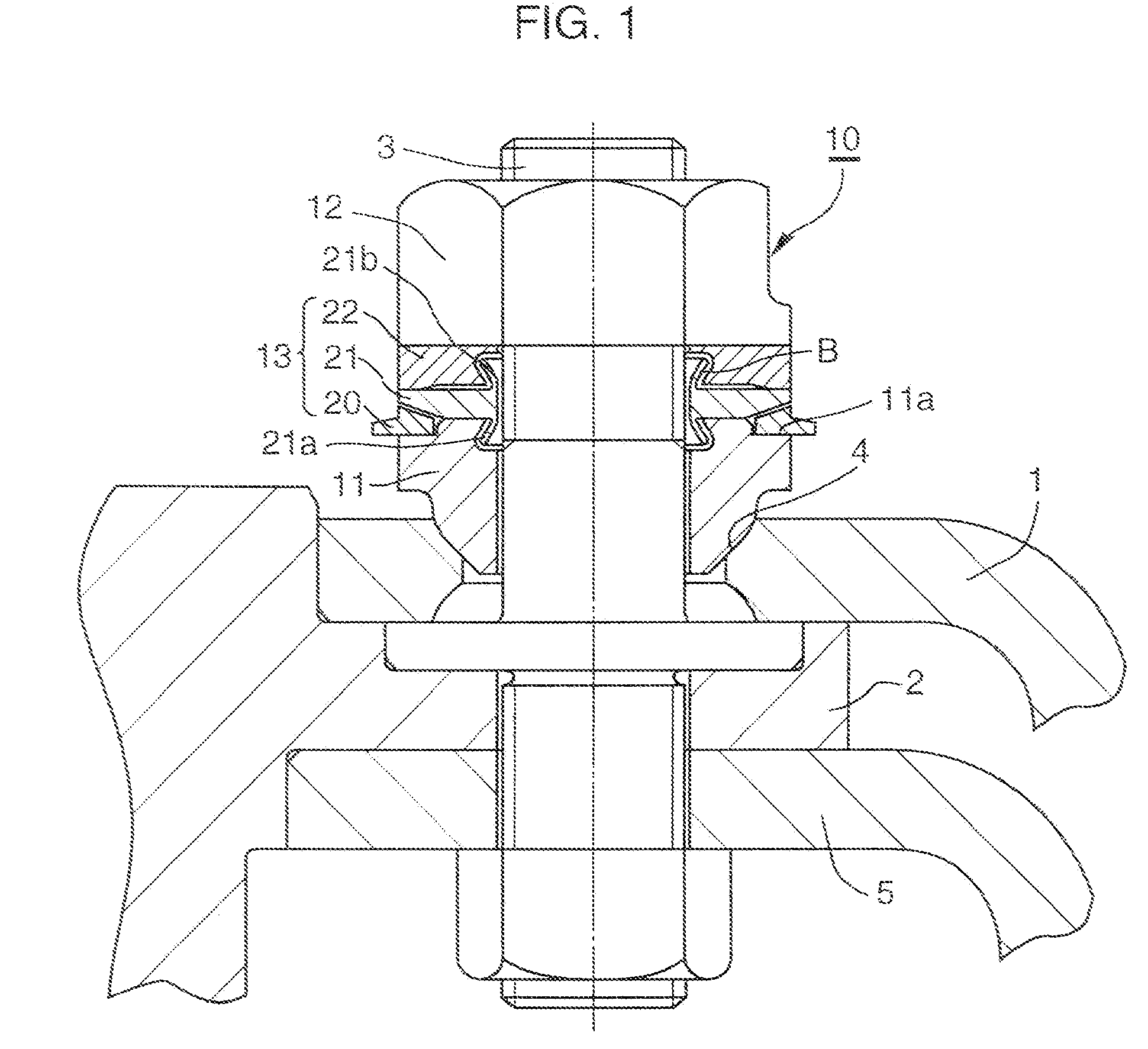
[0116] In Embodiment 1 of the present invention, as illustrated in FIGS. 1 and 18, the ring assembly 13 of the axial force control nut assembly 10 includes the first axial force control ring 20, the elastic deformation ring 21 and the axial force transmitting ring 22 in that order in the direction from the seat member 11 toward the fastening nut 12. The first axial force control ring 20 is disposed between a stepped portion (a stepped recess portion) 11a of a radially outer portion of the seat member 11 and a tapered portion 21c of a radially outer portion of the elastic deformation ring 21 so as to be freely rotatable before the proper axial force is loaded on the bolt 3. The axial force transmitting ring 22 and the elastic deformation ring 21 contact each other at the radially outer portions of the two rings, and there is a gap between the radially inner portions of the two rings.

[0117] The ring assembly 13 does not include the excessive axial force detecting structure A...

embodiment 2

b> And 18

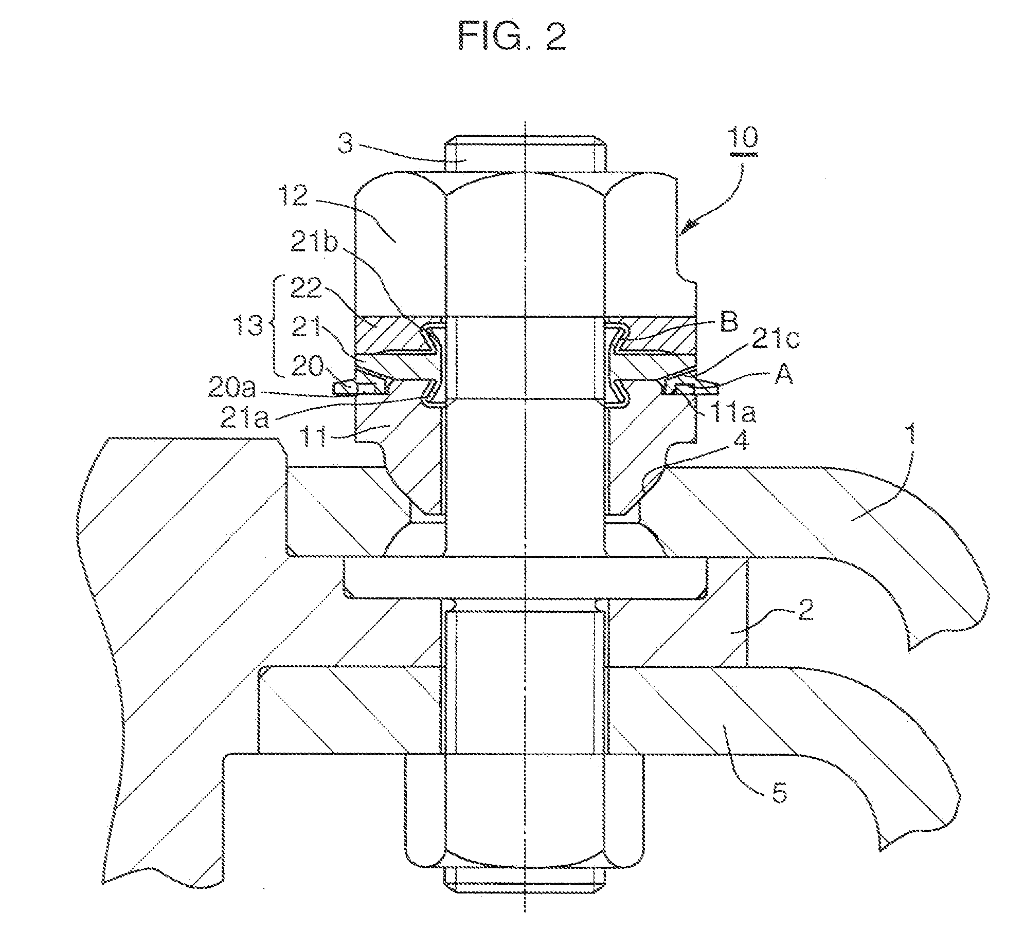
[0123] In Embodiment 2 of the present invention, a groove 20a, acting as the excessive axial force detecting structure A, is added to Embodiment 1 of the present invention.

[0124] In Embodiment 2 of the present invention, as illustrated in FIGS. 1 and 18, the ring assembly 13 of the axial force control nut assembly 10 includes the first axial force control ring 20, the elastic deformation ring 21 and the axial force transmitting ring 22 in that order in the direction from the seat member 11 toward the fastening nut 12. The first axial force control ring 20 is disposed between a stepped portion (a stepped recess portion) 11a of a radially outer portion of the seat member 11 and a tapered portion 21c of a radially outer portion of the elastic deformation ring 21 so as to be freely rotatable before the proper axial force is loaded on the bolt 3. The axial force transmitting ring 22 and the elastic deformation ring 21 contact each other at the radially outer portions of the two...

embodiment 3

b> And 18

[0133] In Embodiment 3 of the present invention, a second axial force control ring 23 acting as the excessive axial force detecting structure A, is added to Embodiment 1 of the present invention.

[0134] In Embodiment 3 of the present invention, as illustrated in FIGS. 3 and 18, the ring assembly 13 of the axial force control nut assembly 10 includes the first axial force control ring 20, the elastic deformation ring 21 and the axial force transmitting ring 22 in that order in the direction from the seat member 11 toward the fastening nut 12. The axial force transmitting ring 22 and the elastic deformation ring 21 contact each other at the radially outer portions of the two rings, and there is a gap between the radially inner portions of the two rings.

[0135] The ring assembly 13 of the axial force control nut assembly 10 further includes a second axial force control ring 23 (the second axial force control ring 23 does not contact the first axial force control ring 20) which...


PUM


Abstract

An axial force control nut assembly 10 includes a seat member 11, a fastening nut 12 rotatable relative to the seat member and a ring assembly 13 disposed between the seat member and the fastening nut. The ring assembly 13 can include one or more rings. At least one of the rings is an axial force control ring 20 is freely rotatable before a bolt axial force reaches the proper axial force and is restricted in rotation after the bolt axial force is equal to or greater than proper axial force. Alternatively or in addition, the ring assembly 13 can include an elastic deformation ring 21. A gap is defined between a radially outer portion of the elastic deformation ring 21 and the seat member 11 before the bolt axial force reaches the proper axial force. The gap between the radially outer portion of the elastic deformation ring 21 and the seat member 11 becomes zero after the bolt axial force is equal to or greater than the proper axial force.

Description

FIELD OF THE INVENTION [0001] The present invention relates to a nut assembly capable of controlling a bolt axial force on the basis of not a torque but an axial force, (hereinafter, an axial force control nut assembly). BACKGROUND OF THE INVENTION [0002] In a vehicle including a truck and a bus, as disclosed in Japanese Patent Publication HEI 11-351225, or as illustrated in FIG. 19 which illustrates a case of a spherical seat member or in FIG. 20 which illustrates a case of a flat seat member, a wheel (for example, a disk wheel) 1 is fixed to a hub 2 of a vehicle by a hub bolt 3 and a hub nut 9. [0003] There are then following drawbacks with the conventional nut: [0004] (a) Since the spherical seat member directly contacts a part to be fixed (for example, a disk wheel), when fastening the nut by applying a torque to the nut, the nut is rotated relative to the part, so that friction is generated at the contact surface. [0005] Due to the friction, transfer of the torque to a bolt axi...

Claims


Application Information

Patent Timeline
Patent Type & Authority Applications(United States)
IPC IPC(8): F16B31/02
CPCF16B31/028F16B31/02
Inventor MARUYAMA, SABUROKIMURA, YOSHIAKIMIYASHITA, SATORUKODAMA, SHOICHIRO
Owner TOPY INDUSTRIES
Why Eureka
Try Eureka