Method of mounting optical component and optical pickup

a technology of optical components and mounting methods, applied in the direction of mountings, optical head manufacture, instruments, etc., can solve the problems of difficult positioning and adjustment of the substrate, easy offset of the position and angle of the substrate, and difficulty in moving the substrate around

Inactive Publication Date: 2008-04-24
TDK CORPARATION
View PDF1 Cites 0 Cited by
  • Summary
  • Abstract
  • Description
  • Claims
  • Application Information

AI Technical Summary

Benefits of technology

[0010]It is therefore an object of the present invention to provide a method of mounting an optical component in which high-precision positioning is possible without the generation of position offset and angle offset when the UV-curable adhesive is cured. Another object of the present invention is to provide a high-performance optical pickup manufactured using such a mounting method.
[0012]In the present invention, the step for fixing the optical component preferably includes a step for applying a UV-curable adhesive so that the optical component is affixed to the mounting surface, and a step for fixing the optical component by irradiating UV light to cure the UV-curable resin. Accordingly, the optical component can be reliably fixed in place in a simple manner.
[0013]In the present invention, the prescribed distance is preferably 300 μm or less, and particularly preferred is a prescribed distance of 1 μm or more and 300 μm or less. If the gap is 300 μm or less and the viscosity of the resin is 20,000 to 50,000 mPa·s, the UV-curable adhesive does not enter between the substrate 13 and the mounting surface 11a, and the position and angle of the substrate 13 do not become offset when the UV-curable resin is cured. When the gap is too wide and the amount of adhesive that is applied is too great, the position is more readily offset due to temperature variation of the optical pickup and the environment after curing. It is advantageous if the gap is 300 μm or less because the position is less likely to become offset at this gap. Also, the substrate is separated from the mounting surface while keeping the substrate parallel with the mounting surface, whereby frictional force with the mounting surface 11a is reduced and the position and angle of the substrate can be finely adjusted with greater ease.
[0015]In the present invention, the optical component is preferably a substrate on which a photoelement is mounted. The light source, lens, and other components of the optical system are mounted in the housing. Therefore, accurate positioning that has accounted for mounting errors of the light source, lens, and other components is required when the photoelement is mounted, and when the photoelement is mounted in accordance with the above-described method, the positioning accuracy of the photoelement can be assured, and a high-performance optical pickup can be achieved. In this case, the photoelement is preferably one that is used for recording and reproduction, focus control, and tracking control. It is particularly preferred that the photoelement comprise a main beam photodetector for receiving a main beam reflected by an optical disc, and a sub-beam photodetector for receiving a sub-beam reflected by the optical disc, and that the focus servo and the tracking servo be carried out by detecting the output of the main beam photodetector and the sub-beam detector.
[0017]Thus, in accordance with the present invention, a method of mounting an optical component can be provided in which high-precision mounting is possible in a simple manner without the generation of position offset and angle offset when the UV-curable adhesive is cured.

Problems solved by technology

However, there is a problem in that the position and angle of the substrate readily become offset when the UV-curable adhesive is cured because resin enters into the space between the substrate and the mounting surface when the prescribed width is 0.1 to 0.5 mm.
On the other hand, when the substrate is made to adhere to the mounting surface, frictional force with the mounting surface is considerable, and there is therefore a problem in that the substrate is therefore difficult to move around and the position is difficult to adjust.

Method used


Image

  • Method of mounting optical component and optical pickup
  • Method of mounting optical component and optical pickup
  • Method of mounting optical component and optical pickup

Examples


Embodiment Construction

[0025]Preferred embodiments of the present invention will be described in detail hereinafter with reference to the accompanying drawings. In the present embodiment, a substrate on which a photoelement (PDIC) is mounted is used as an example of an optical component, and a method of mounting the substrate on the housing of an optical pickup will be described.

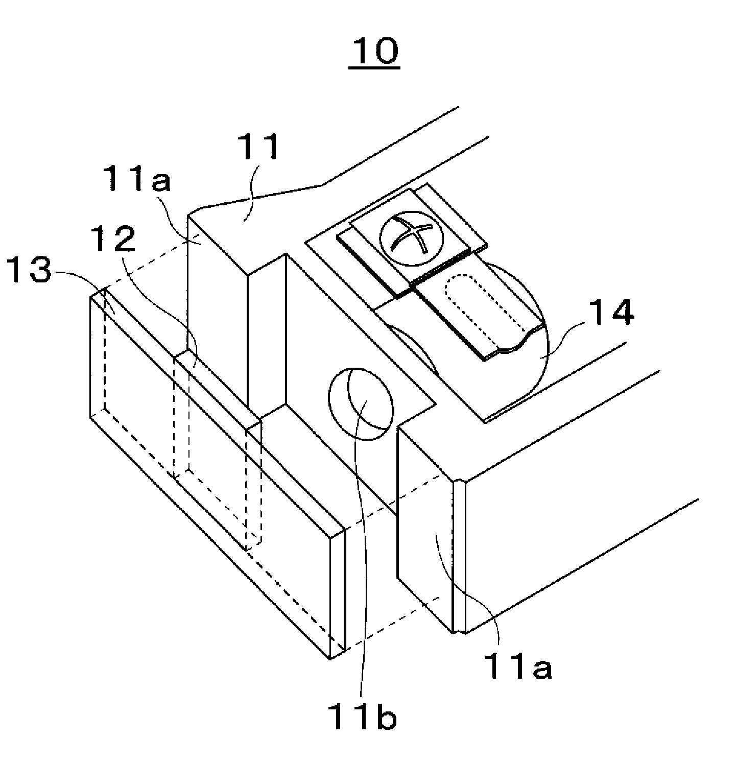
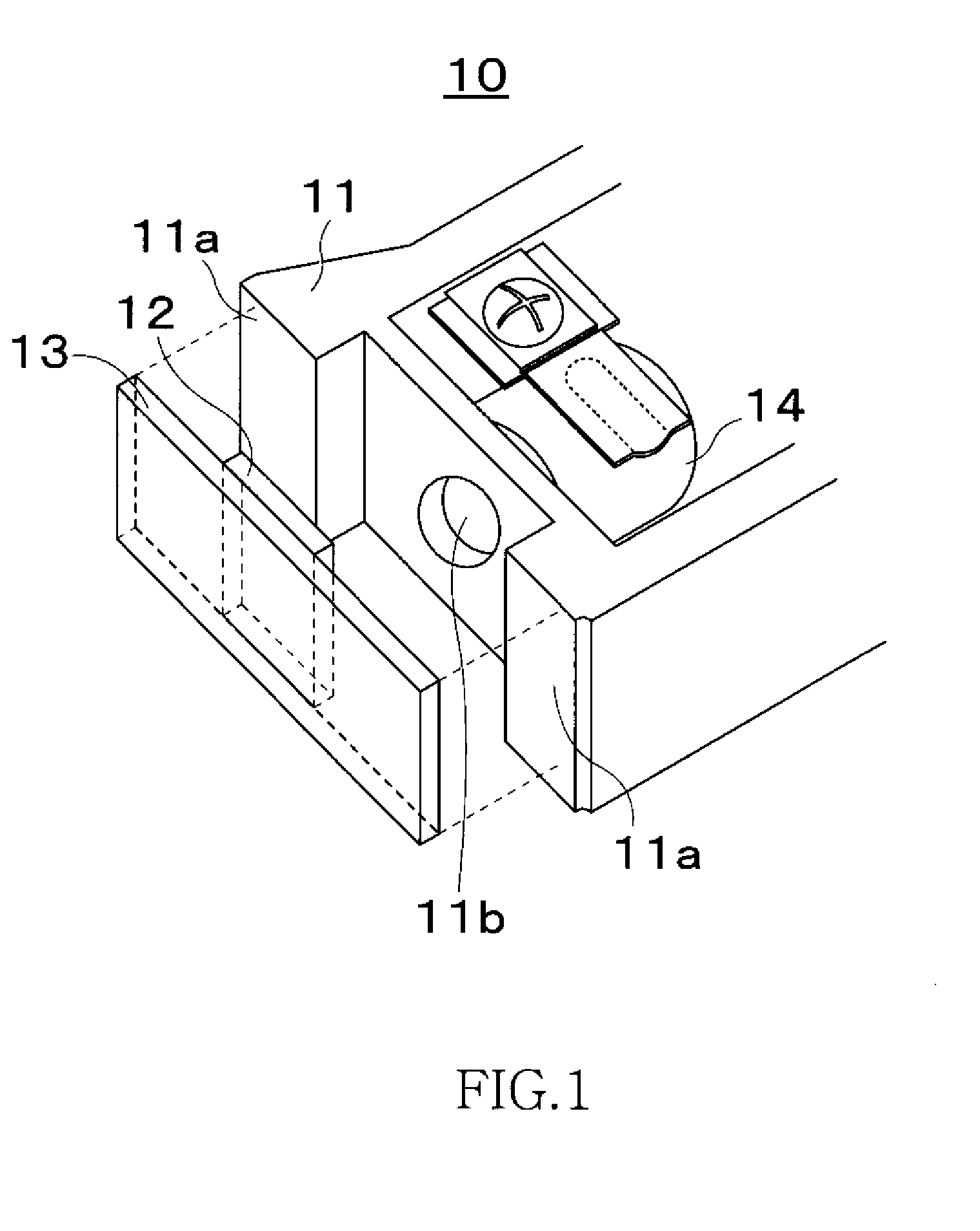
[0026]FIG. 1 is a schematic exploded perspective view that partially shows the configuration of an optical pickup.

[0027]As shown in FIG. 1, an optical pickup 10 comprises a housing 11 in which a light source, lens, and other components of an optical system are mounted. A mounting surface 11a for mounting a substrate 13 on which a photoelement 12 is mounted is formed on the side surface of the exterior of the housing 11. The two ends of the substrate 13 are mounted on the mounting surface 11a, whereby the photoelement 12 is mounted on the housing 11. In this case, the photoelement 12 is disposed on the optical axis of the optical s...


PUM

PropertyMeasurementUnit
Distanceaaaaaaaaaa
Distanceaaaaaaaaaa
Angleaaaaaaaaaa

Abstract

A method of mounting an optical component is provided with the steps of pressing an optical component to a mounting surface of a housing, separating the optical component from the mounting surface within a prescribed distance while remaining parallel with the mounting surface, adjusting the position and angle of the optical component, and fixing the optical component to the mounting surface. The prescribed distance is preferably 1 μm or more and 300 μm or less. The step of fixing the optical component includes the steps of applying a UV-curable adhesive so that the optical component is affixed to the mounting surface, and fixing the optical component by irradiating UV light to cure the UV-curable resin.

Description

CROSS-REFERENCE TO RELATED APPLICATIONS[0001]This application was first filed on Oct. 18, 2006, as Japanese Patent Application No. 2006-284381, which application is hereby incorporated herein by reference in its entirety and from which application foreign priority is hereby claimed under 35 U.S.C. §119(a)-(d).TECHNICAL FIELD[0002]The present invention relates to a method of mounting an optical component when a photoelement or another optical component is fixed in a housing. The present invention also relates to an optical pickup manufactured using the method of mounting an optical component.BACKGROUND OF THE INVENTION[0003]An optical recording and reproducing apparatus that records and reproduces optical discs and optical magnetic discs is provided with an optical pickup for recording information in prescribed areas on a track formed along the circumferential direction of the disc, or reproducing the information recorded in the prescribed areas on a track. The optical pickup is prov...

Claims


Application Information

Patent Timeline
IPC IPC(8): G02B7/02H01S4/00
CPCG02B7/025Y10T29/49002G11B7/22G11B7/131
Inventor NAKAGOMI, SHOOKA, TEIICHIRO
Owner TDK CORPARATION
Why Eureka
Try Eureka