Electromagnetic clutch and compressor fitted with the electromagnetic clutch

An electromagnetic clutch and armature technology, applied in the direction of magnetic drive clutches, clutches, non-mechanical drive clutches, etc.

Inactive Publication Date: 2005-03-16
MITSUBISHI HEAVY IND LTD
View PDF0 Cites 3 Cited by
  • Summary
  • Abstract
  • Description
  • Claims
  • Application Information

AI Technical Summary

Problems solved by technology

Therefore, when the coil 104 is energized, it is excited to make the armature plate 105 contact the end face of the drive rotor 103, thereby generating difficult noise

Method used


Image

  • Electromagnetic clutch and compressor fitted with the electromagnetic clutch
  • Electromagnetic clutch and compressor fitted with the electromagnetic clutch
  • Electromagnetic clutch and compressor fitted with the electromagnetic clutch

Examples


Embodiment Construction

[0053] Detailed description of the preferred embodiment

[0054] The first embodiment of the present invention will be described below with reference to the accompanying drawings. However, the present invention is not limited to these examples.

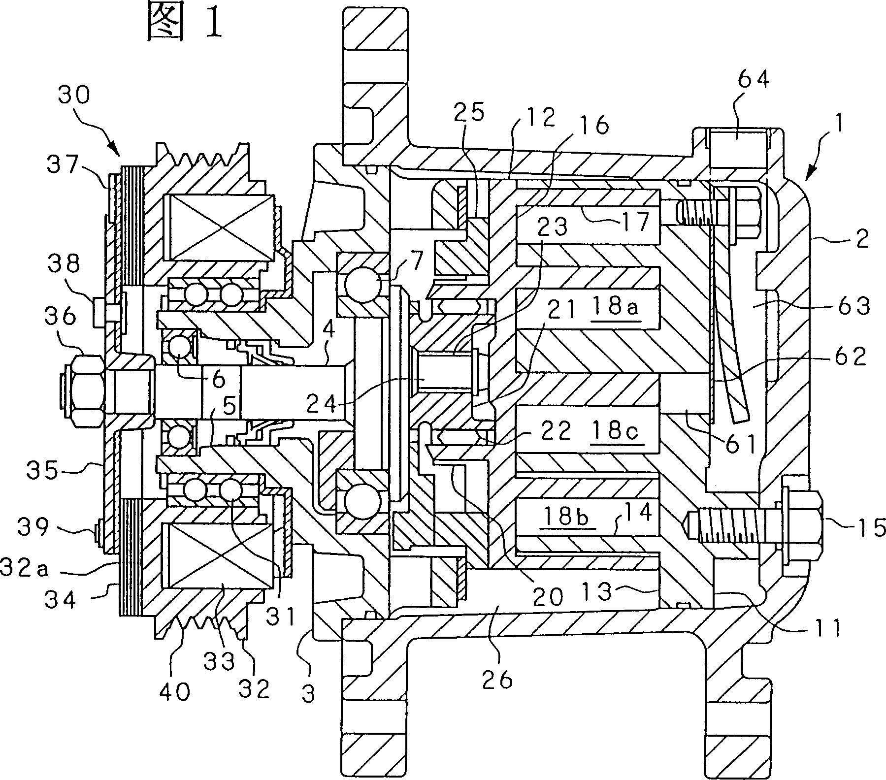
[0055] Fig. 1 is a longitudinal sectional view of a compressor of the present invention.

[0056] In the compressor shown in FIG. 1, a housing 1 is composed of a cup-shaped main body 2 and a front housing 3 fixed by bolts not shown in the figure.

[0057] The scroll compressor components are composed of a fixed scroll 11 and an orbiting scroll 12 , and are disposed inside a cup-shaped main body 2 .

[0058] The fixed scroll 11 is provided with an end plate 13 and a spiral wrap 14 protruding from an inner surface of the end plate 13 . The end plate 13 is fixed on the cup-shaped main body 2 by bolts 15 . The orbiting scroll 12 is provided with an end plate 16 and a spiral wrap 17 protruding from an inner surface of the end plate 16 ...


PUM


Abstract

The present invention aims to provide an electromagnetic clutch capable of decreasing the impact noise generated when the armature plate and the driving rotor are coupled. An electromagnetic clutch in the present invention comprises a driving rotor including a coil, and an armature having an armature plate that is disposed facing this driving rotor and having the same axis of rotational thereas, and when a voltage is applied to excite coil, the end face of driving rotor and the armature plate are attached together by coil's magnetic force, thereby coupling driving rotor and armature. Armature plate comprises a plurality of metal thin plates (plate members) laminated together, and at least a part of the plate members being connected each other.

Description

technical field [0001] The invention relates to an electromagnetic clutch, in particular to an electromagnetic clutch used for an automobile air-conditioning compressor. Background of the invention [0002] Figure 16 It is a longitudinal section view of an ordinary electromagnetic clutch. [0003] The electromagnetic clutch 100 is installed in an automobile air conditioner compressor. The electromagnetic clutch 100 is intermittently mechanically connected to the compressor and an unillustrated drive source. The electromagnetic clutch 100 is provided at the front end 101 of the compressor front casing. [0004] The driving rotor 103 is rotatably supported on the outer peripheral surface of the front end 101 via the clutch bearing 102 . The coil 104 is provided inside the drive rotor 103 . The armature disk 105 is arranged coaxially facing the drive rotor 103 . [0005] The hub 106 is secured to an extension of the compressor drive shaft 112 by a nut 107 . One end of th...

Claims


Application Information

Patent Timeline
IPC IPC(8): F16D27/07F16D27/00F16D27/06
CPCF16D2027/008F16D27/06F16D27/00
Inventor 服部诚谷垣龙平河田稔富增和宏关田真澄安藤博秀
Owner MITSUBISHI HEAVY IND LTD
Why Eureka
Try Eureka