
Inhalation apparatus

a technology of inhalation apparatus and inhalation chamber, which is applied in the direction of breathing masks, breathing protection, other medical devices, etc., can solve the problems of inability to accurately control the amount of inhalation agent, the inability to keep the diameter of inhalation agent droplets at the optimal value, and the change in the droplet diameter due to evaporation, so as to keep the inhalation agent droplet diameter constant regardless of the use environment, and efficiently dose the user

Inactive Publication Date: 2008-04-24
CANON KK
View PDF0 Cites 12 Cited by
  • Summary
  • Abstract
  • Description
  • Claims
  • Application Information

AI Technical Summary

Benefits of technology

The present invention is a portable inhalation apparatus that can keep the size of inhaled droplets constant regardless of environmental conditions and efficiently dose the user. It includes an airflow path, an agent discharger, and a humidifier located outside the airflow path. The humidifier prevents the evaporation of the agent droplets, resulting in the user inhaling droplets with a constant diameter. The humidifier does not interfere with the user's inhalation process.

Problems solved by technology

However, in the case where an agent is discharged in the form of minute droplets, the diameter of droplets changes due to evaporation.
Therefore, it is difficult to keep the diameter of agent droplets at the optimum value.
As a result, the amount of agent that the user inhales cannot be accurately controlled.
Located inside the airflow path, it can interfere with the inhalation airflow and therefore can interfere with ease of inhalation of the user.
This leads to wasteful consumption of energy in the inhalation apparatus and an increase in weight and size of the inhalation apparatus, and consequently degrades the portability of the inhalation apparatus.

Method used


Image

  • Inhalation apparatus
  • Inhalation apparatus
  • Inhalation apparatus

Examples


first embodiment

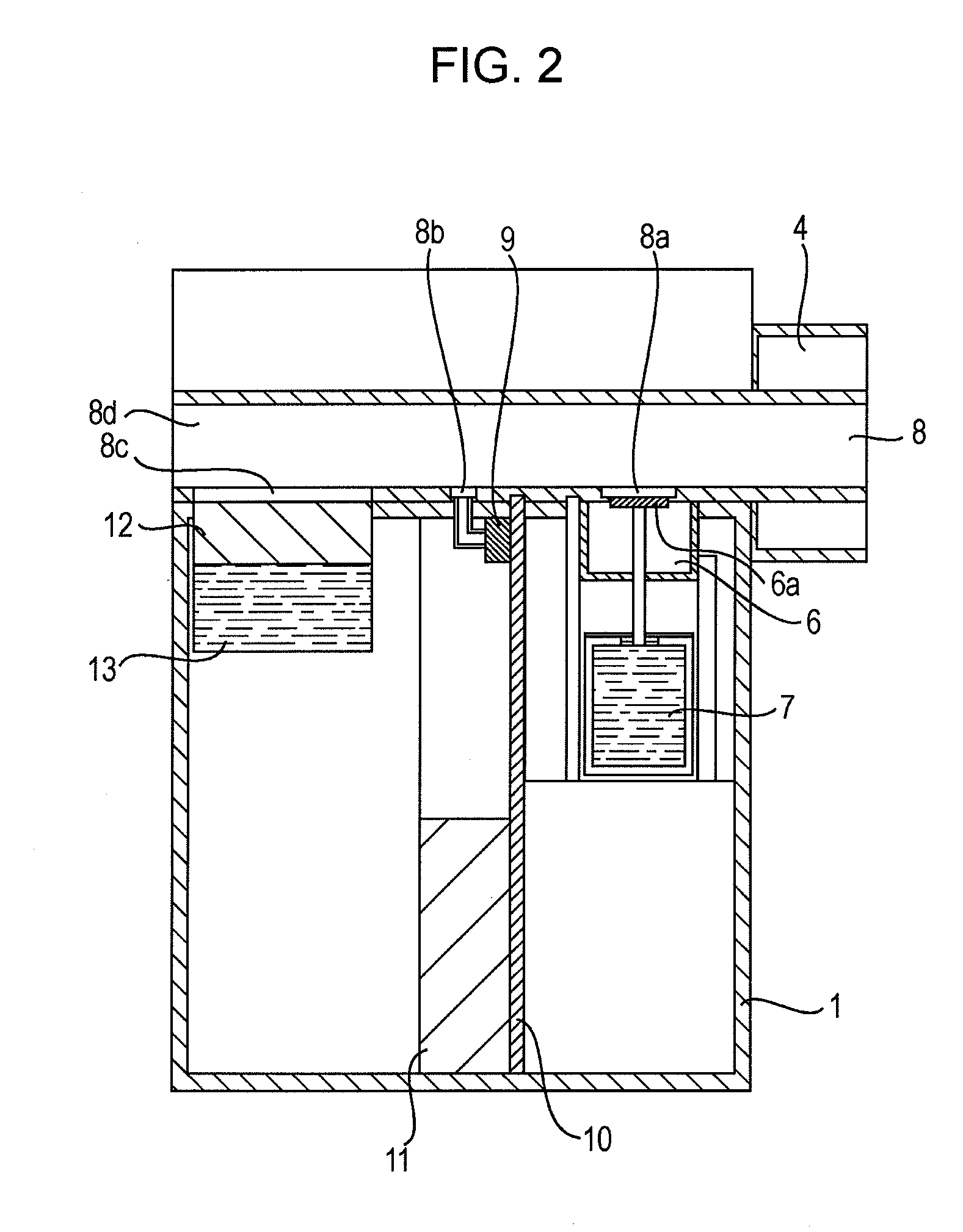
[0039]A first embodiment will be described with reference to FIG. 2. In the inhalation apparatus according to this embodiment, a porous body 12 is located upstream of the discharge head 6a in the inhalation airflow in the airflow path 8. The porous body 12 serves as a liquid holder and a humidifier that supplies moisture for humidifying the airflow generated by the use's inhalation. The porous body 12 communicates with the liquid tank 13. By tilting the inhalation apparatus, liquid is supplied to the porous body 12. The water held in the porous body 12 evaporates, thereby generating water vapor. This water vapor flows into the airflow path 8 through a humidification port 8c, thereby humidifying the inhalation airflow.

[0040]The porous body 12 is formed of a material capable of holding water, for example, a sponge.

[0041]A film that transmits vapor but does not transmit water can be placed at the humidification port 8c so that water does not leak into the airflow path 8.

[0042]The user ...

second embodiment

[0044]FIG. 3 is a sectional view of an inhalation apparatus according to a second embodiment. This embodiment differs from the first embodiment in that it uses a nebulizer 22 that discharges mist such as water vapor. The nebulizer 22 is supplied with water from a liquid tank 13 communicating therewith. The nebulizer 22 is controlled by a control board 10 and can include a heater so that water vapor can be easily generated. The nebulizer 22 can discharge not only water vapor but also another gas or liquid into the airflow path 8. For example, the nebulizer 22 can discharge flavored gas together with water vapor so that the user can inhale easily.

third embodiment

[0045]FIG. 4 is a sectional view of an inhalation apparatus according to a third embodiment. This embodiment differs from the first embodiment in that an enlarged flow path 38 having an enlarged cross-sectional area is formed at the position where the humidification port 8c of the airflow path 8 is located. That is, the cross-sectional area of a part of the airflow path where the humidifier is located is larger than the cross-sectional area of a part of the airflow path where the discharge head 6a is located. In the case where this method is used, the flow velocity in the enlarged flow path part is smaller. Therefore, inhaled air is humidified more efficiently.


PUM


Abstract

In order to control the amount of evaporation of discharged agent droplets and so that a user can inhale agent droplets having a constant diameter regardless of use environment, an inhalation apparatus includes an airflow path communicating with a suction port through which the user inhales an agent, an agent discharging portion configured to discharge an agent supplied to the airflow path, and a humidifier located outside the airflow path and configured to humidify an airflow in the airflow path generated by an inhalation of the user.

Description

BACKGROUND OF THE INVENTION[0001]1. Field of the Invention[0002]The present invention relates to an inhalation apparatus that discharges an agent such as medicine, fragrance, or nicotine so that the user can inhale it.[0003]2. Description of the Related Art[0004]A method for dosing using an inhalation apparatus is known. Unlike an injection, such dosing through the respiratory system does not cause pain. Such an inhalation apparatus can also serve as a portable terminal including a storage unit that stores information on the user including the user's medical record and prescription, and a discharge device that discharges an agent in the form of minute droplets so that the user can inhale them. Such an inhalation apparatus can also include a discharge control unit that makes the discharge device discharge the agent according to the user's inhalation profile so that the user can inhale the agent according to the prescription information (see WO95 / 01137 and WO02 / 04043).[0005]In inhalat...

Claims


Application Information

Patent Timeline
Patent Type & Authority Applications(United States)
IPC IPC(8): A61M11/00
CPCA61M11/005A61M11/041A61M15/02A61M16/16A61M2016/0018A61M2016/0027A61M15/025A61M2205/583A61M2205/7536A61M2205/8206A61M11/001A61M11/042A61M2205/3592
Inventor OOIDA, JUNICHIHATANAKA, TAKAHIROSHINJO, KATSUHIKO
Owner CANON KK
Learn More