
Circuitry for supplying electrical power to loads

a load and circuit technology, applied in the field of circuitry, can solve the problems of increasing losses, consuming space, and reducing the efficiency of load supply, and achieving substantially below line peak regulated output is difficult, if not impossible, and can only be achieved with a pure boost topology

Active Publication Date: 2008-04-17
IDEAL IND LIGHTING LLC
View PDF34 Cites 287 Cited by
  • Summary
  • Abstract
  • Description
  • Claims
  • Application Information

AI Technical Summary

Benefits of technology

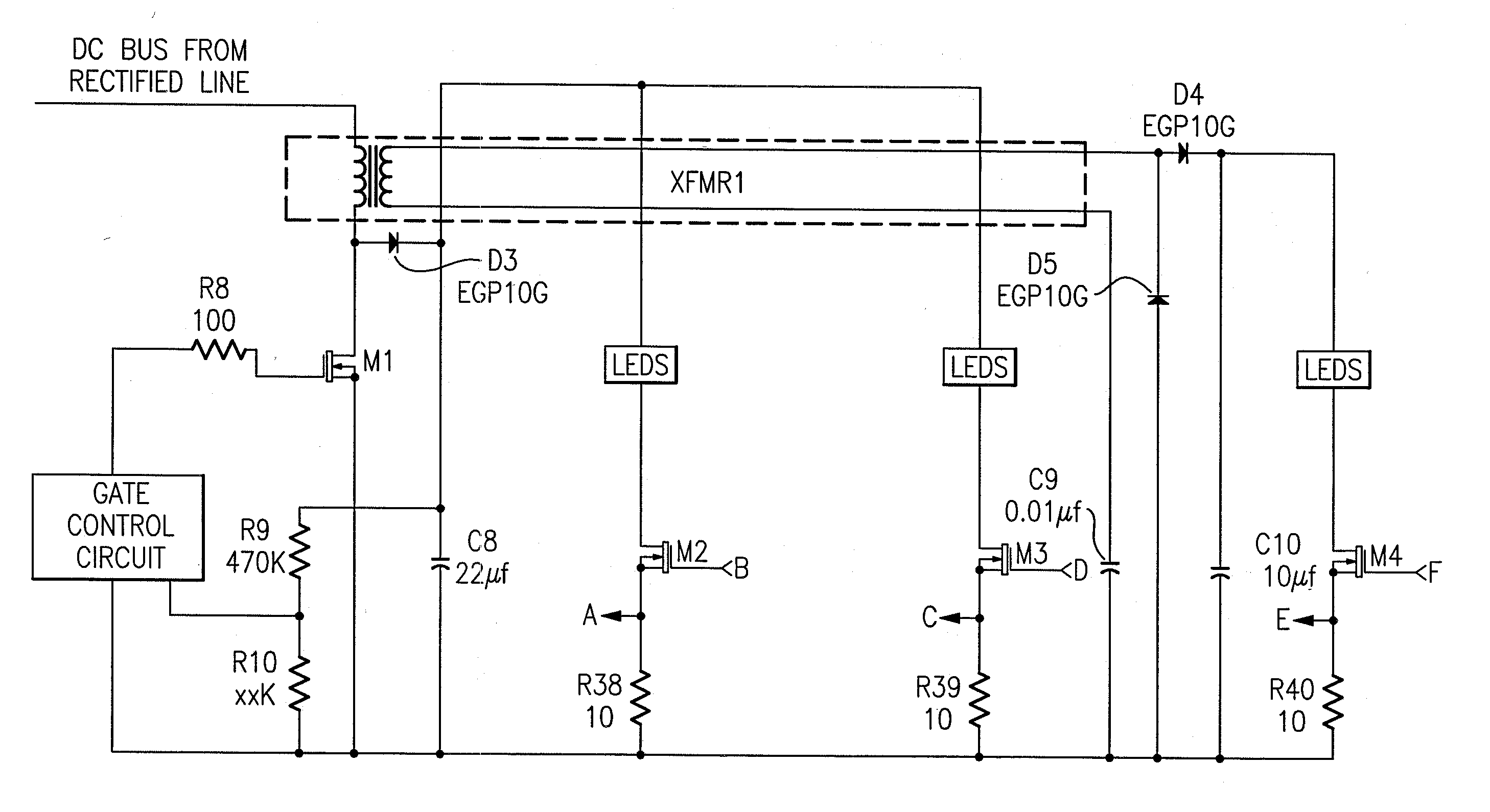
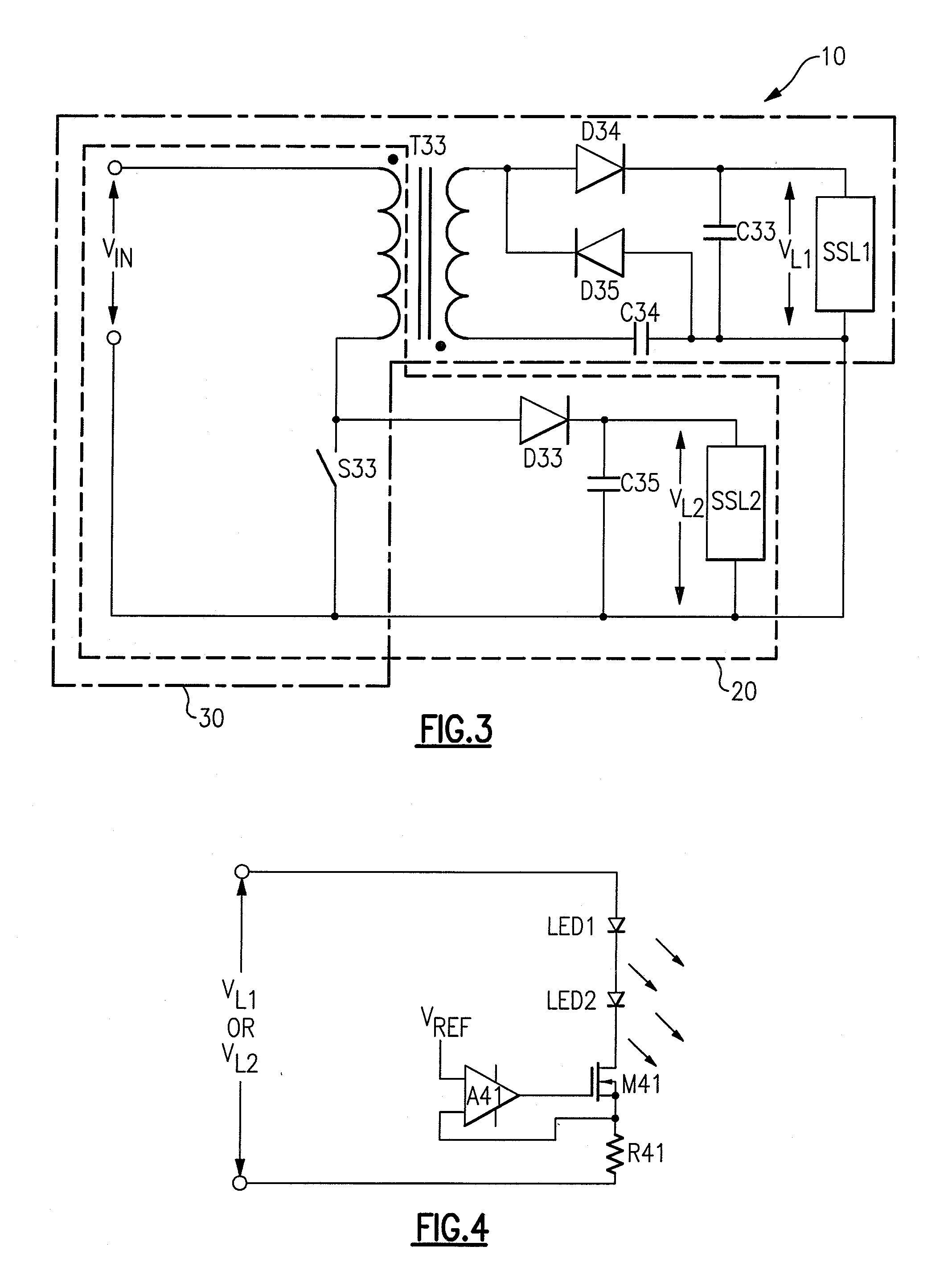
[0009] The boost / flyback arrangement makes it possible to use the boost topology for a switch mode power supply to create output voltages above input line peak, while the flyback winding simultaneously creates an output voltage below input line peak. A regulated output substantially below line peak is difficult, if not impossible, to achieve with a pure boost topology. A flyback topology would mean a large number of secondary turns (relative to primary) to achieve a voltage above input line peak, which may be costly, consume space, and increase losses. Accordingly, a combination boost / flyback topology is provided. A second winding, electrically isolated from the primary boost winding is constructed on the transformer bobbin. The number of turns of this winding is less than the number of turns of the primary boost winding, resulting in a lower output voltage at load. The combination of boost winding and secondary winding represents a unique combination.

Problems solved by technology

A regulated output substantially below line peak is difficult, if not impossible, to achieve with a pure boost topology.
A flyback topology would mean a large number of secondary turns (relative to primary) to achieve a voltage above input line peak, which may be costly, consume space, and increase losses.

Method used


Image

  • Circuitry for supplying electrical power to loads
  • Circuitry for supplying electrical power to loads
  • Circuitry for supplying electrical power to loads

Examples


Embodiment Construction

[0041] The present invention now will be described more fully hereinafter with reference to the accompanying drawings, in which embodiments of the invention are shown. However, this invention should not be construed as limited to the embodiments set forth herein. Rather, these embodiments are provided so that this disclosure will be thorough and complete, and will fully convey the scope of the invention to those skilled in the art. Like numbers refer to like elements throughout. As used herein the term “and / or” includes any and all combinations of one or more of the associated listed items.

[0042] The terminology used herein is for the purpose of describing particular embodiments only and is not intended to be limiting of the invention. As used herein, the singular forms “a”, “an” and “the” are intended to include the plural forms as well, unless the context clearly indicates otherwise. It will be further understood that the terms “comprises” and / or “comprising,” when used in this s...


PUM


Abstract

A power supply, comprising a boost converter which provides voltage to a first load, and a flyback converter which provides voltage to a second load and which utilizes an inductive element of the boost converter as a primary winding of a transformer of the flyback converter. Also, a power supply comprising a MOSFET which is disposed between solid state elements and a second reference potential and which controls current flowing through the solid state elements. Also, a circuit comprising a transformer, a first circuit portion comprising the primary winding of the transformer and a second circuit portion comprising the secondary winding of the transformer. Also, a power supply comprising means for using a common transformer for providing a boost converter and a flyback converter. Also, a power supply comprising a transformer, means for providing a boost converter utilizing the transformer, and means for providing a flyback converter utilizing the transformer.

Description

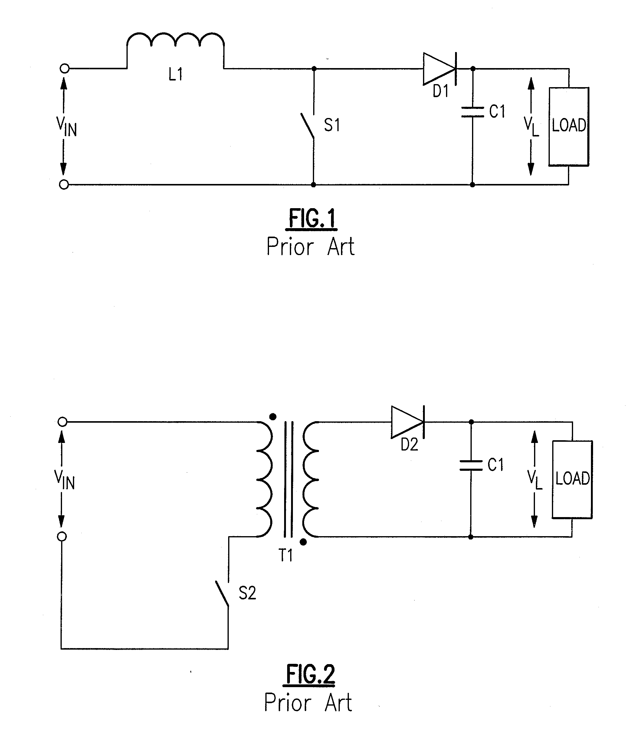
CROSS-REFERENCE TO RELATED APPLICATIONS [0001] This application claims the benefit of U.S. Provisional Patent Application No. 60 / 844,325, filed Sep. 13, 2006, the entirety of which is incorporated herein by reference.FIELD OF THE INVENTION [0002] The present invention relates to circuitry for supplying electrical power to one or more loads. In some aspects, the present invention relates to circuitry for supplying electrical power to drive one or more solid state light emitting elements, e.g., LEDs. BACKGROUND OF THE INVENTION [0003] Types of conventional switching mode power supplies include a boost converter topology and a flyback converter topology. A conventional boost converter topology is illustrated in FIG. 1. A boost converter is a power converter which provides an output voltage that is greater than its input voltage (i.e. VL>Vin). The boost converter depicted in FIG. 1 includes an energy storage element, such as the inductor L1, a switching element S1, a flyback diode D1...

Claims


Application Information

Patent Timeline
Patent Type & Authority Applications(United States)
IPC IPC(8): H05B41/36H02J1/00H02M3/335
CPCH02M3/335
Inventor MYERS, PETER JAY
Owner IDEAL IND LIGHTING LLC
Learn More