
Rotary tool-equipped tool rest

Inactive Publication Date: 2008-04-17
OKUMA CORP
View PDF11 Cites 2 Cited by
  • Summary
  • Abstract
  • Description
  • Claims
  • Application Information

AI Technical Summary

Benefits of technology

[0009]The present invention solves the above-described problems, and has an object to provide a rotary tool-equipped tool rest with a low production cost, and the tool rest can prevent a spindle core of a rotary tool from shifting from a spindle core of a tool coupling spindle with high accuracy, has a high rigidity in the frontward and backward directions in a turret, and can be subjected to high accuracy processing. Further, the tool rest has a simple mechanism to engage a phase determining pin in the turret to a non-swiveling housing, is hardly troubled, and easily maintained.
[0012]According to a turret type rotary tool-equipped tool rest described in claim 1, a turret and a non-swiveling housing are directly coupled in a shortest root by the phase determining pin. Thus, shifting of the spindle core of the rotary tool from the spindle core of the tool coupling spindle can be effectively prevented with remarkably high accuracy. In addition, when the present invention is applied to an elongated rotary tool-equipped tool rest in which a holding spindle of the non-swiveling housing is locked so as not to rotate at a position distant from the turret, the tool rest can obtain the same effect without an influence of rigidity or accuracy of the holding spindle of the non-swiveling housing. Further, since a coupling mechanism to clamp the turret with respect to the non-swiveling housing has a so-called three pieces coupling, the turret does not necessarily move frontwardly and backwardly at the time of releasing engaging. Thus, since rigidity in the frontward and backward directions of the turret is high, the tool rest can be subjected to high accuracy processing.
[0013]According to a turret type rotary tool-equipped tool rest described in claim 2, a driving mechanism of the phase determining pin is simple, and a driving force is transmitted from a driving source to the phase determining pin without loss. Thus, a driving response of the phase determining pin is quick. Further, the driving mechanism of the phase determining pin is hardly troubled, and is easily maintained. Furthermore, since there are few parts needed for the driving mechanism of the phase determining pin, the production cost is low.

Problems solved by technology

Thus, since rigidity in the frontward and backward directions of the turret is low, there is a problem that the tool rest is hardly subjected to high accuracy processing.
Further, since a mechanism to engage the phase determining pin in the turret to the non-swiveling housing is complicated, there are problems such as the turret tool rest is easily troubled and hardly maintained.

Method used


Image

  • Rotary tool-equipped tool rest
  • Rotary tool-equipped tool rest
  • Rotary tool-equipped tool rest

Examples


Embodiment Construction

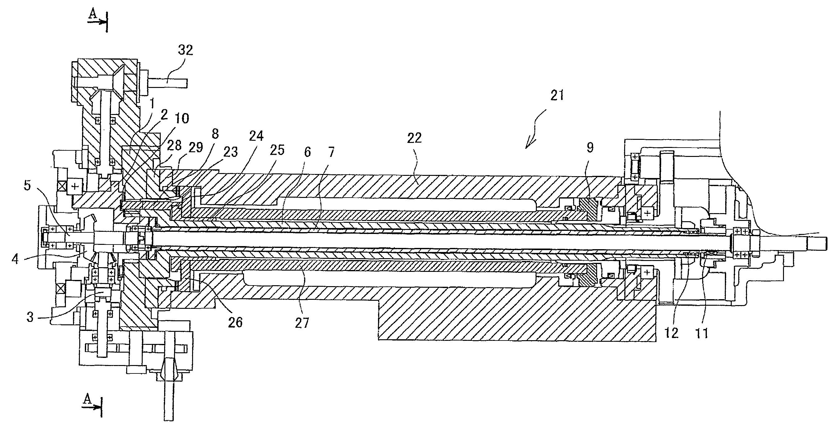
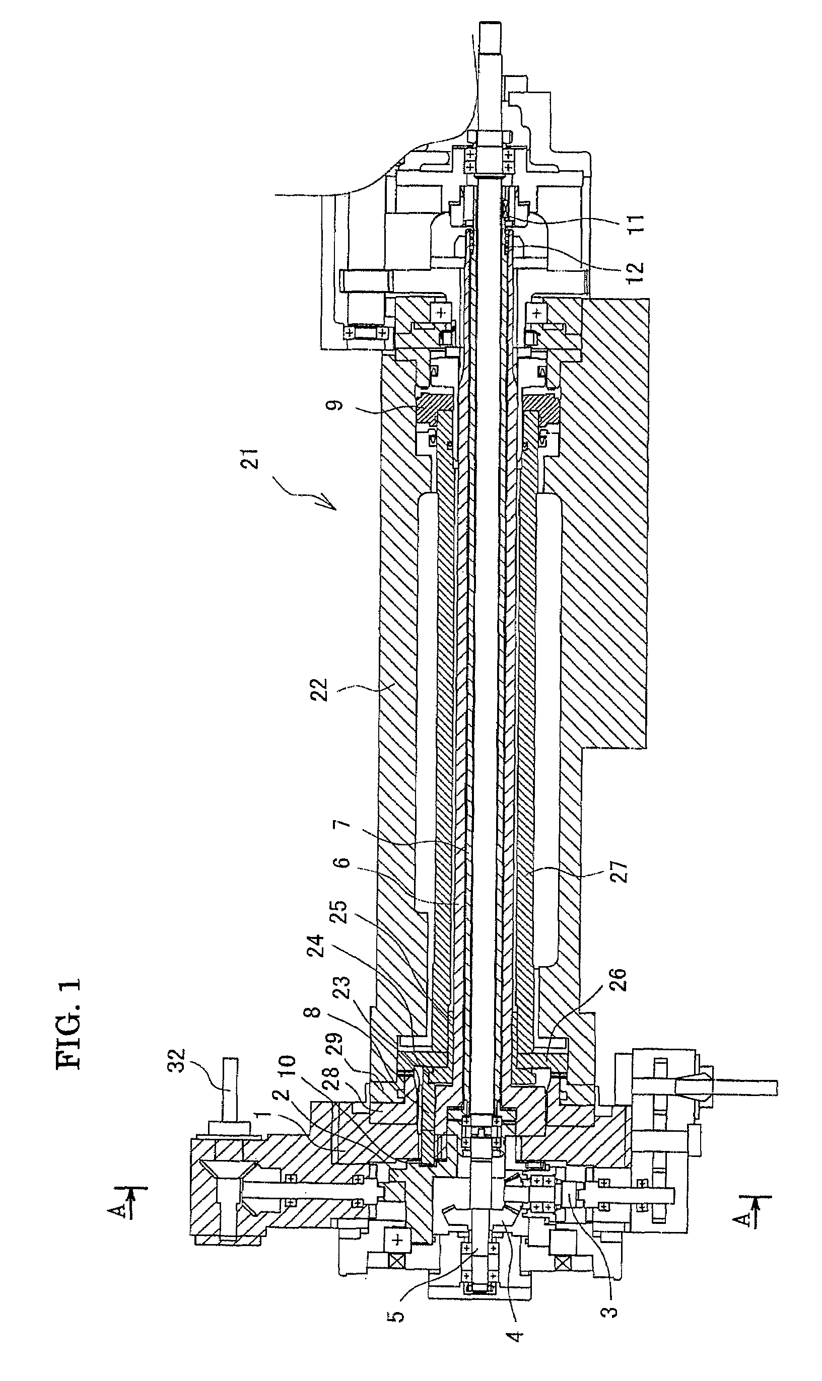
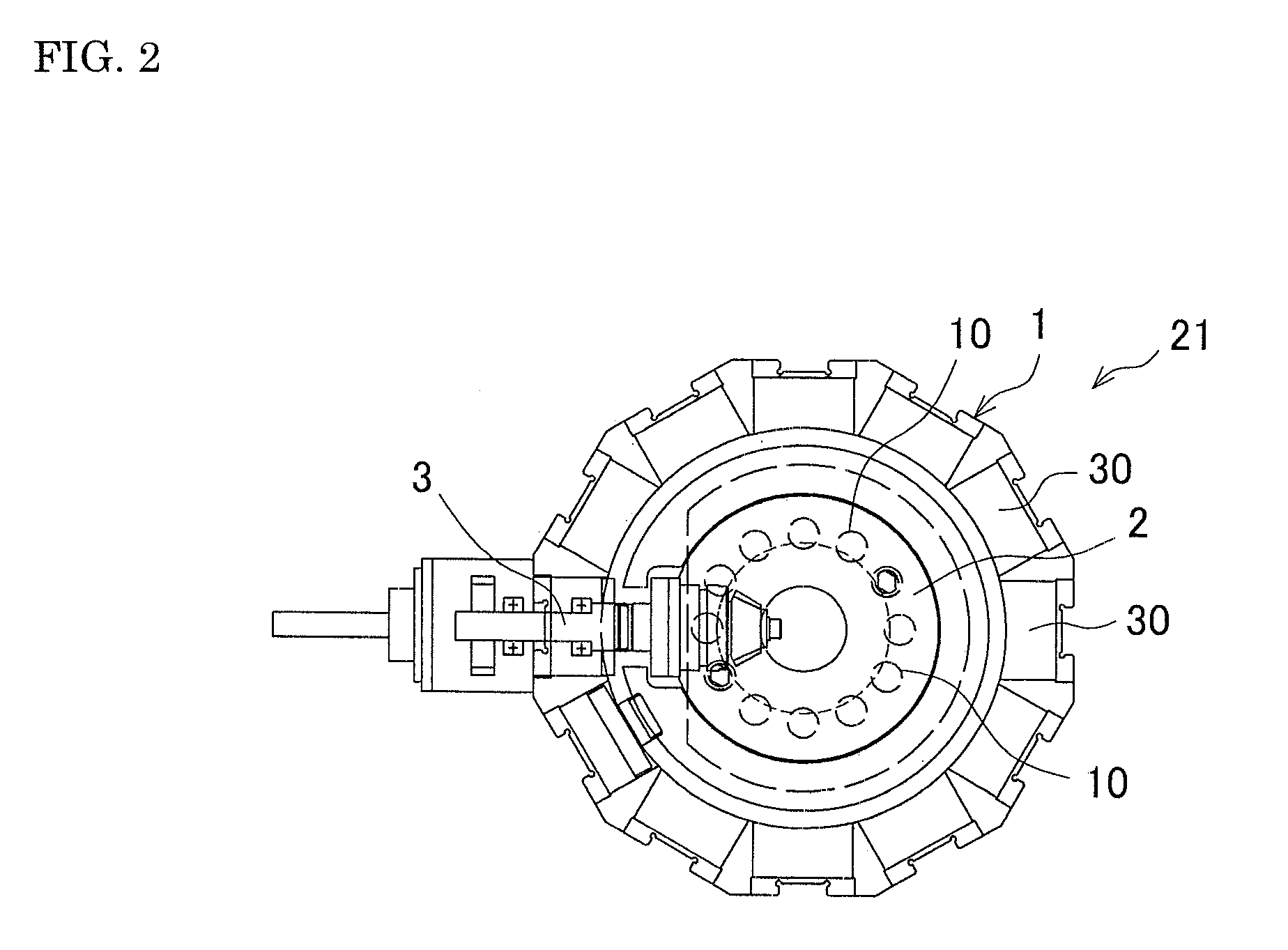
[0016]One embodiment of a rotary tool-equipped tool rest of the present invention will be described in detail below referring to the drawings. FIG. 1 illustrates a vertical cross section of a rotary tool-equipped tool rest, and FIG. 2 illustrates a cross section taken along the A-A line in FIG. 1. A rotary tool-equipped tool rest 21 includes a turret 1 rotatably provided at a front end of a tool rest main body 22, in which tools are attached with a turret 1. A long tool driving spindle 5 is rotatably supported by a tool driving motor, which is not illustrated, in the tool rest main body 22. Further, a long cylindrical housing holding spindle 7 is provided at an outer periphery of the tool driving spindle 5, and a base end of the housing holding spindle 7 is strongly fixed at the tool rest main body 22 by a key 11. In addition, the base end of the housing holding spindle 7 includes a spring 12 to frontwardly energize a non-swiveling housing 2 described below.

[0017]Further, a long cyl...


PUM


Abstract

In a rotary tool-equipped tool rest 1, a movable member 27 is made to move frontwardly when a turret 1 is clamped with respect to a non-swiveling housing 2 after swiveling and indexing. Then, a phase determining pin 8 provided in the turret 1 is made to project and engaged with the non-swiveling housing 2. Further, a coupling mechanism to clamp the turret 1 with respect to the non-swiveling housing 2 has three-pieces coupling including a first coupling member 26, a second coupling member 28 and a third coupling member 29.

Description

[0001]This application claims the benefit of Japanese Patent Application Number 2006-277957 filed on Oct. 11, 2006, the entirety of which is incorporated by reference.BACKGROUND OF THE INVENTION[0002]1. Field of the Invention[0003]The present invention relates to a rotary tool-equipped tool rest including a swiveling mechanism for swiveling a turret, and a tool rotating mechanism for rotating and driving a plurality of rotary tools attached to a tool station of the turret.[0004]2. Description of the Background Art[0005]A conventional rotary tool-equipped tool rest includes a non-swiveling housing having a tool coupling spindle to transmit a driving force of a driving spindle, where a rotary tool attached to the turret is coupled with a tool coupling spindle only at the time of indexing a station processed by a turret. In this conventional rotary tool-equipped tool rest, when the turret is swiveled and indexed, a spindle core of a rotary tool and a spindle core of tool coupling spind...

Claims


Application Information

Patent Timeline
IPC IPC(8): B23B29/24
CPCB23B29/323B23B2270/60Y10T29/5155Y10T74/1488Y10T82/2508Y10T29/5154Y10T82/2587Y10T82/2524
Inventor NEO, SHINYAOSAKI, TSUTOMUSHOZUSAWA, TAKAHIKO
Owner OKUMA CORP
Learn More