
Loudspeaker and microphone based on the principle of "The Center of Percussion"

a technology of loudspeaker and microphone, which is applied in the direction of electromechanical transducers, diaphragm construction, transducer diaphragms, etc., can solve the problems of reducing the efficiency of the transducer, affecting the performance of the transducer, so as to improve the sound separation, improve the sound absorption, and improve the density and distribution of mass

Inactive Publication Date: 2008-04-10
ILIES ANDREI +1
View PDF11 Cites 5 Cited by
  • Summary
  • Abstract
  • Description
  • Claims
  • Application Information

AI Technical Summary

Benefits of technology

[0013]The present invention also describes a microphone, which presents an elongated member. The sound waves will bring a mainly transversal oscillation mode to the membrane, resulting in a more efficient energy transfer.
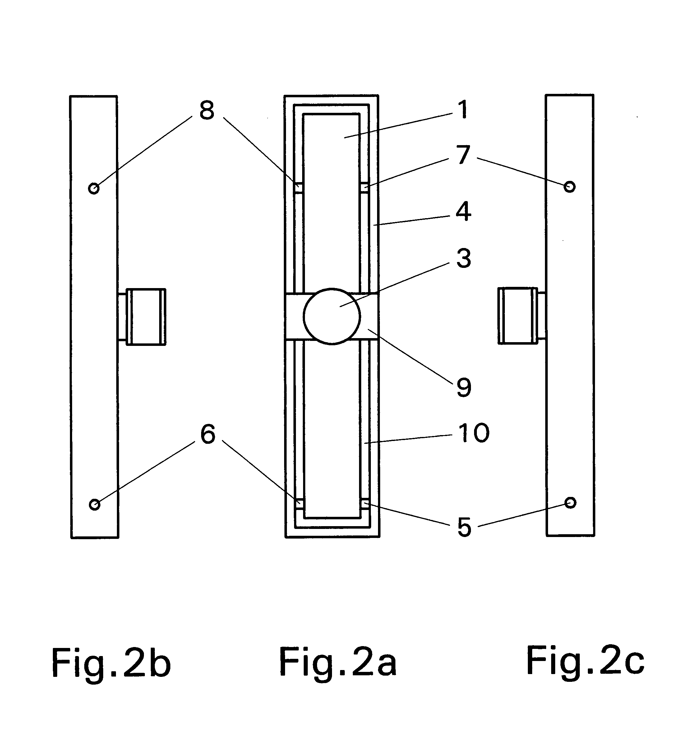
[0019]In a second alternative to the preferred embodiment of the invention the two sides apart from the center of mass of the entire oscillating member can be considered as moving their centers of mass in a translation and only their parts outside from their centers of mass towards the ends of the entire oscillating member will rotate around the respective centers of mass of the very parts of the oscillating member. This state will bring about two additional points where the inertial forces show balance in a particular case, that is, no reaction in the center of mass of the very parts of the entire oscillating member on each side of the center of mass of the entire oscillating member. These two points, if used as locations for joints, would bring about an outstanding dynamic stability for the entire oscillating member, translated in acoustic terms, the highest quality of transferred vibrations attainable from the system. The voice coil in this case is best placed in the center of mass of the entire oscillating member.
[0021]Another alternative to the preferred embodiment of the invention is to create a cavity or cavities inside the oscillating member to enable a closer control of density and distribution of mass along the system. Also, the replacement of the air inside the cavity or cavities with a suitable fluid will improve the sound absorption inside the oscillating member. A rubber bladder is installed in the proximity of the oscillating member, connected to the cavity or cavities to compensate for the volume variation of the gas due to changes in temperature. Also, creating a certain degree of vacuum in the cavity or cavities inside the oscillating member or membrane will bring an improved sound separation between the different targeted areas of the system.
[0022]In another alternative to the preferred embodiment of the invention a loudspeaker is held in a horizontal position with the gap of the magnet assembly surrounding the voice coil facing upwards. In this position, having the central part of the magnet assembly provided with an opening that communicates with the front side of the oscillating member, the cavity of the magnet assembly can be filled with a heat exchanging fluid other than magnetic fluid. The submerged voice coil will be able to handle increased power loads.
[0023]In another alternative to the preferred embodiment of the invention a stream of gas like air is sent across the coil of a dynamic loudspeaker in order to improve the cooling of the coil. In another alternative to the preferred embodiment of the invention, the round shaped coil of a dynamic transducer is changed to a out of circular shape in order to decrease the inductance of the coil, and this way decrease the inductive reactance of the coil at high frequencies, targeting an increase of output and improved phase response.
[0024]In another alternative to the preferred embodiment of the invention, the voice coil form, so called former, is placed between two successive layers of the voice coil. The improved connection of the voice coil elements in this case avoids the exfoliation of the coil windings due to thermal expansion and sealant failure, rendering the voice coil physically indestructible.

Problems solved by technology

The main disadvantage of the first category is the predominant piston-like motion of the oscillating member.
Their membrane is also very thin compared to their other dimensions, being highly transparent to the sound, allowing for the sound in opposition of phase, produced on the rear side of the oscillating member to cancel part of the sound produced on the front side of the speaker, diminishing the efficiency of the transducer.
Even with considerable damping provisions, this phenomenon poses clear limitations on the transducer's performance.
The disadvantage of a generally stiff and thick membrane is that it is not able to handle the propagation of transversal oscillations in two perpendicular directions without excessively stressing their body and introducing distortions over a permissible limit.
Certain designs of planar loudspeakers have adopted an elongated shape of the oscillating member, with noticeable advantages, but the unnecessary internal stressing of their poorly balanced membranes still brings about a high level of distortion.

Method used


Image

  • Loudspeaker and microphone based on the principle of "The Center of Percussion"
  • Loudspeaker and microphone based on the principle of "The Center of Percussion"
  • Loudspeaker and microphone based on the principle of "The Center of Percussion"

Examples


Embodiment Construction

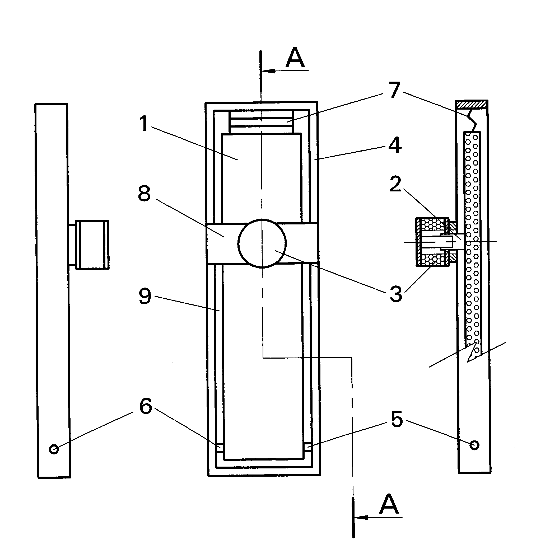
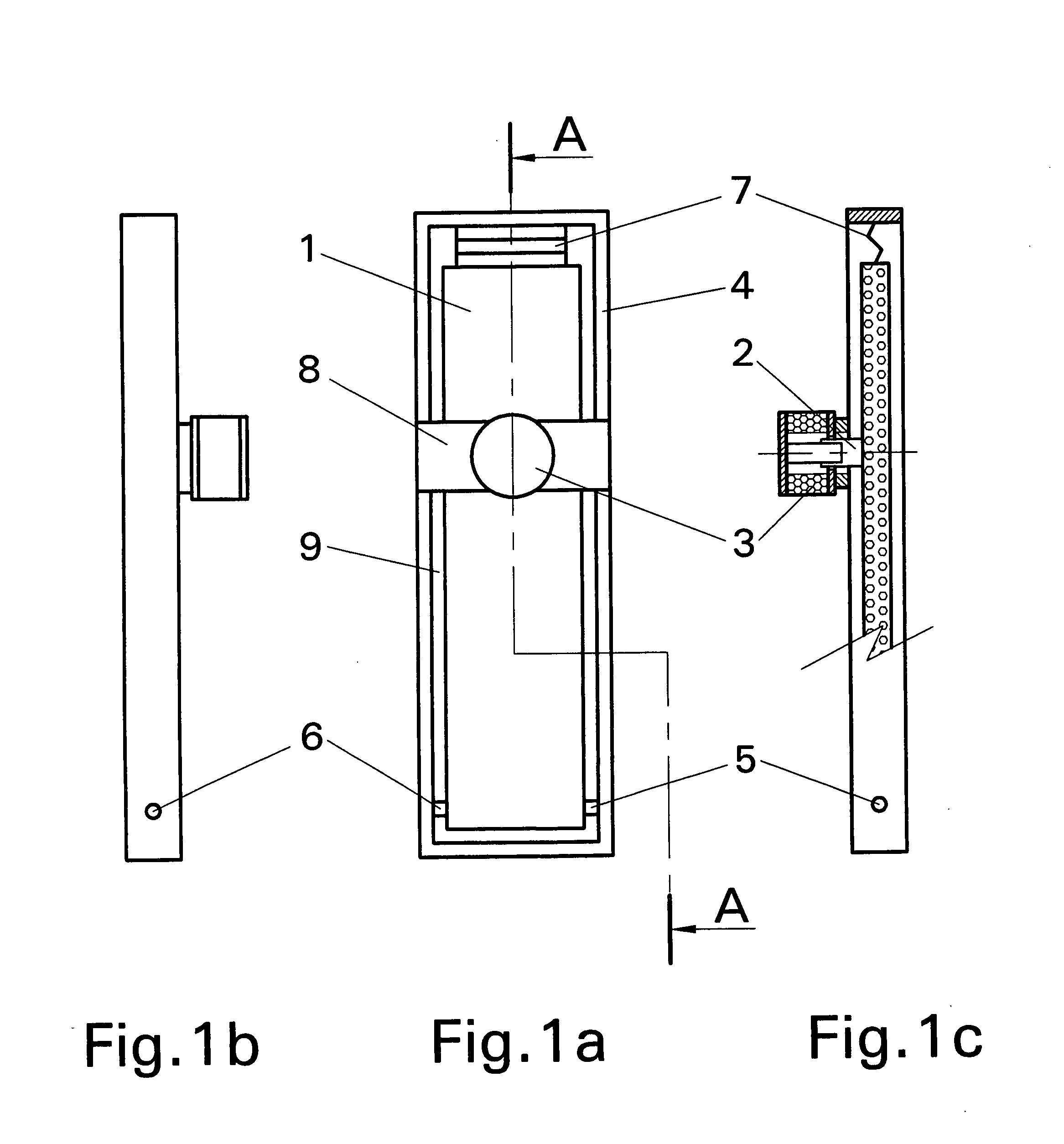
[0057]FIG. 1a is showing the electromechanical transducer, in particular a loudspeaker or a microphone as the oscillating member (1) surrounded by the solid frame (4). The magnet assembly (3) is mounted on the bridge (8). The pair of joints (5) and (6) is holding the first end of the oscillating member (1). The flexible element (7) is holding the second end of the oscillating member (1) and attaches to the frame (4). An air gap (9) is present between the frame (4) and the oscillating member (1). The position of the voice coil is centered over the width of the oscillating member and is in the area of the center of percussion of the entire oscillating member about the axis of the joints (5) and (6) in one alternative to the preferred embodiment of the invention. The vibration, induced either way to the oscillating member will not be transferred into the pair of joints (5)-(6) according to the principle of “The Center of Percussion”. It looks as if the vibration is not affected by the ...


PUM


Abstract

A transducer of electrical oscillations to mechanical oscillations or mechanical oscillations to electrical oscillations, mainly a loudspeaker or a microphone, having in general an elongated oscillating member attached by joints to a surrounding structure in areas of points or lines of specific dynamic balance, like one end, center of mass, center of equal rotational inertia, center of percussion about a certain axis of rotation. At least one actuator is mounted in the area of these balancing points or lines. In an alternative to the preferred embodiment of the invention, the oscillating member is built to incorporate at least one cavity filled with air or a fluid different from air or having a certain degree of vacuum in it. In an alternative to the preferred embodiment of the invention the transducer is placed in a position to favor the retention of a heat exchanging fluid, other than magnetic fluid, inside the actuator.The incorporation of a coil other than circular targets the reduction of coil inductance to increase the transducer's performance.A symmetrical constructed assembly brings about improved physical stability to voice coils.

Description

BACKGROUND OF THE INVENTION[0001]This invention relates to loudspeakers and microphones of every type. In general any kind of electromechanical and mechanical transducers that can reach outside the acoustic range are to be considered.[0002]The dynamic loudspeakers, having a voice coil placed in the gap of an electromagnet or permanent magnet are mainly of two categories. The first category is the cone type, flat radiator and the soft and hard domes. The second category is the planar speaker.[0003]The main disadvantage of the first category is the predominant piston-like motion of the oscillating member. Their membrane is also very thin compared to their other dimensions, being highly transparent to the sound, allowing for the sound in opposition of phase, produced on the rear side of the oscillating member to cancel part of the sound produced on the front side of the speaker, diminishing the efficiency of the transducer.[0004]The dynamic transducers can be compared to a physical pen...

Claims


Application Information

Patent Timeline
IPC IPC(8): H04R25/00
CPCH04R7/045H04R7/08H04R7/20H04S2400/09H04R17/02H04R2440/05H04R9/041
Inventor ILIES, ANDREIDRAGAN, LUMINITA
Owner ILIES ANDREI
Learn More