Semiconductor device, step-down chopper regulator, and electronic equipment
- Summary
- Abstract
- Description
- Claims
- Application Information
AI Technical Summary
Benefits of technology
Problems solved by technology
Method used
Image
Examples
first embodiment
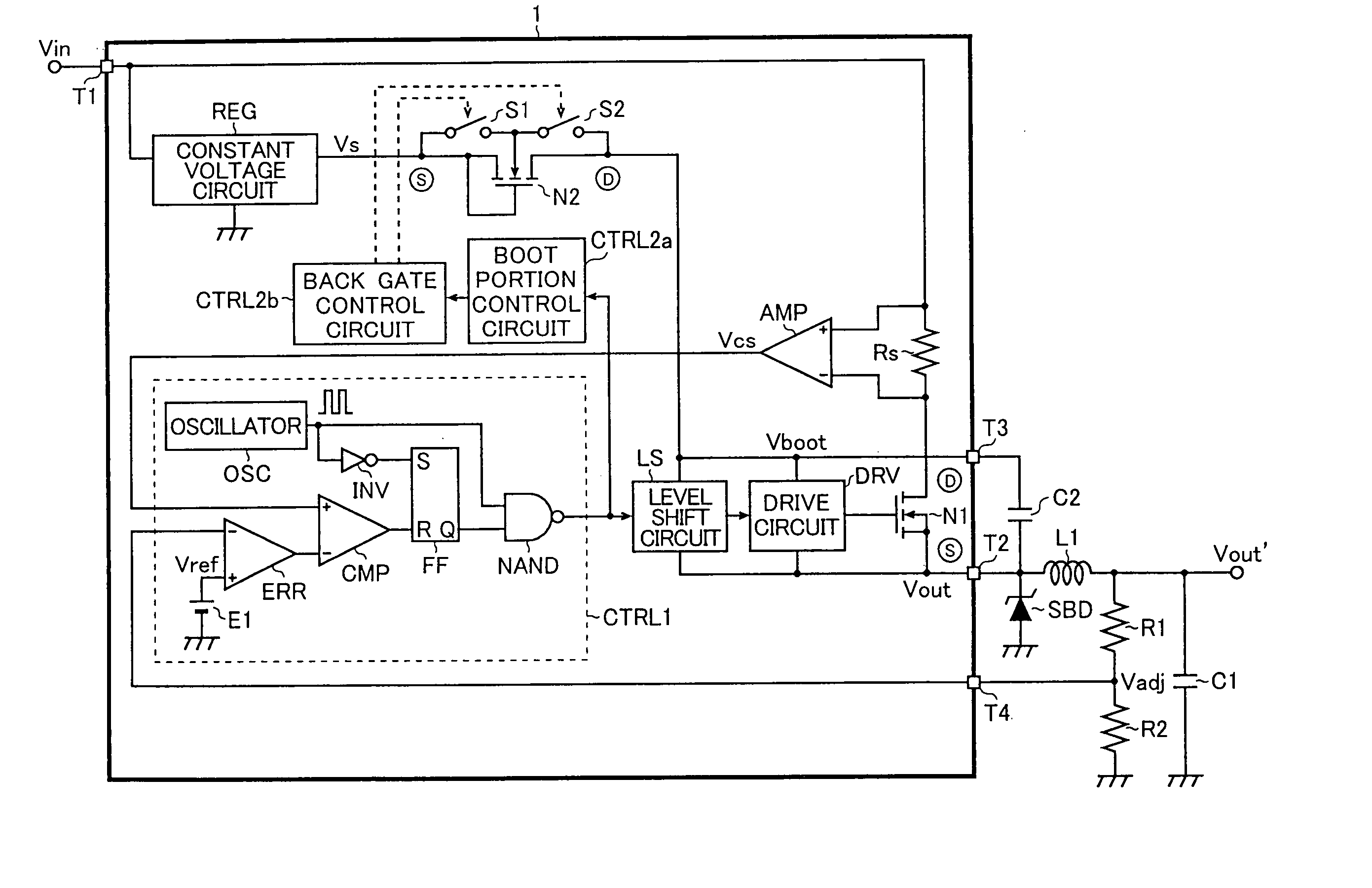
[0041] First, a step-down chopper regulator (a step-down switching regulator) according to the present invention will be described in detail.
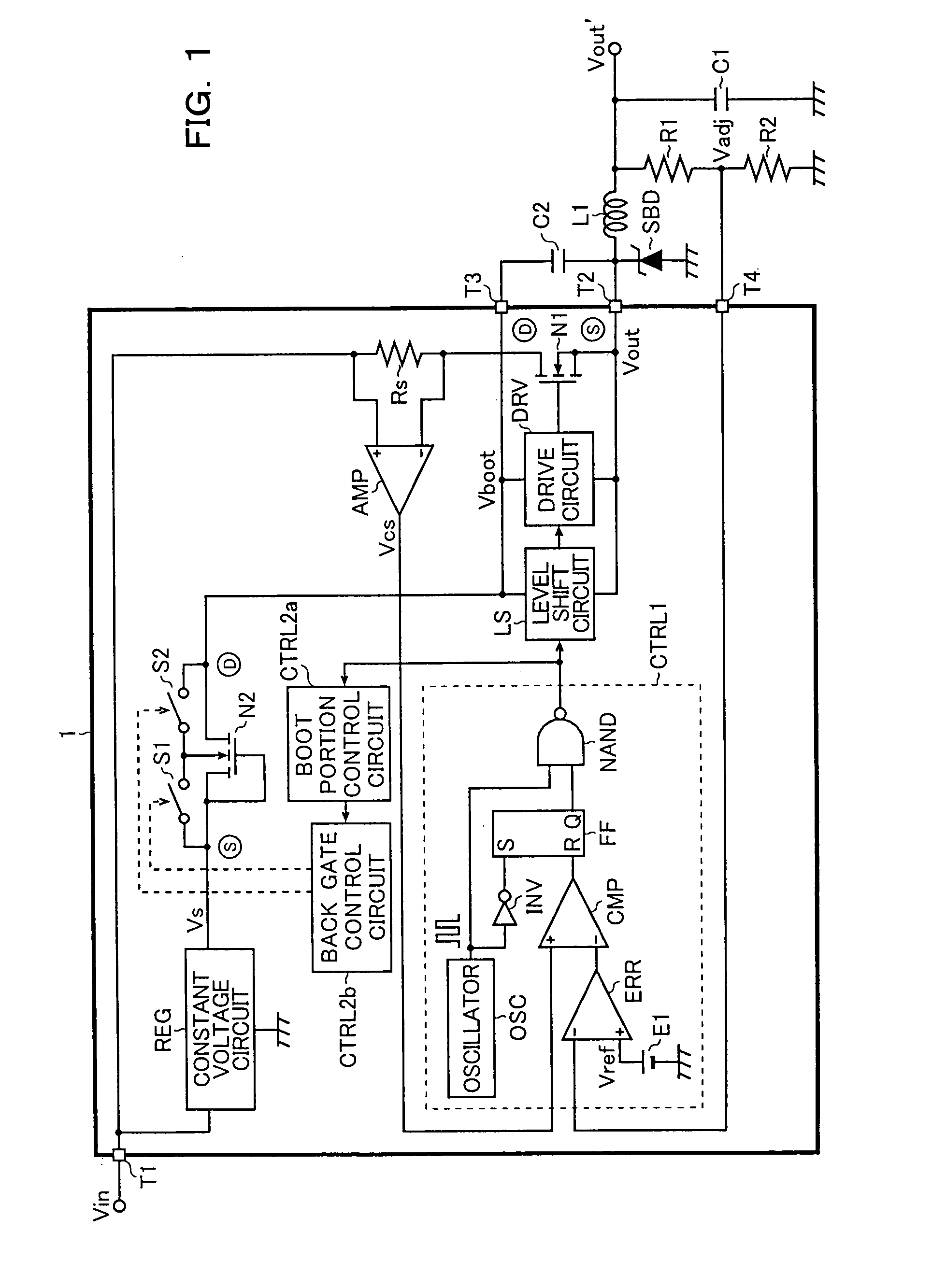
[0042]FIG. 1 is a block diagram showing the first embodiment of the step-down chopper regulator (step-down switching regulator) according to the present invention.
[0043] As shown in FIG. 1, the step-down chopper regulator according to the present invention is made up of a semiconductor device (a step-down chopper regulator IC) 1, an output inductor L1, an output capacitor C1, a Schottky barrier diode SBD, a boot capacitor C2, and resistors R1 and R2. It steps down an input voltage Vin so as to generate a desired smooth output voltage Vout′, which is supplied to a load (not shown) as a drive voltage.
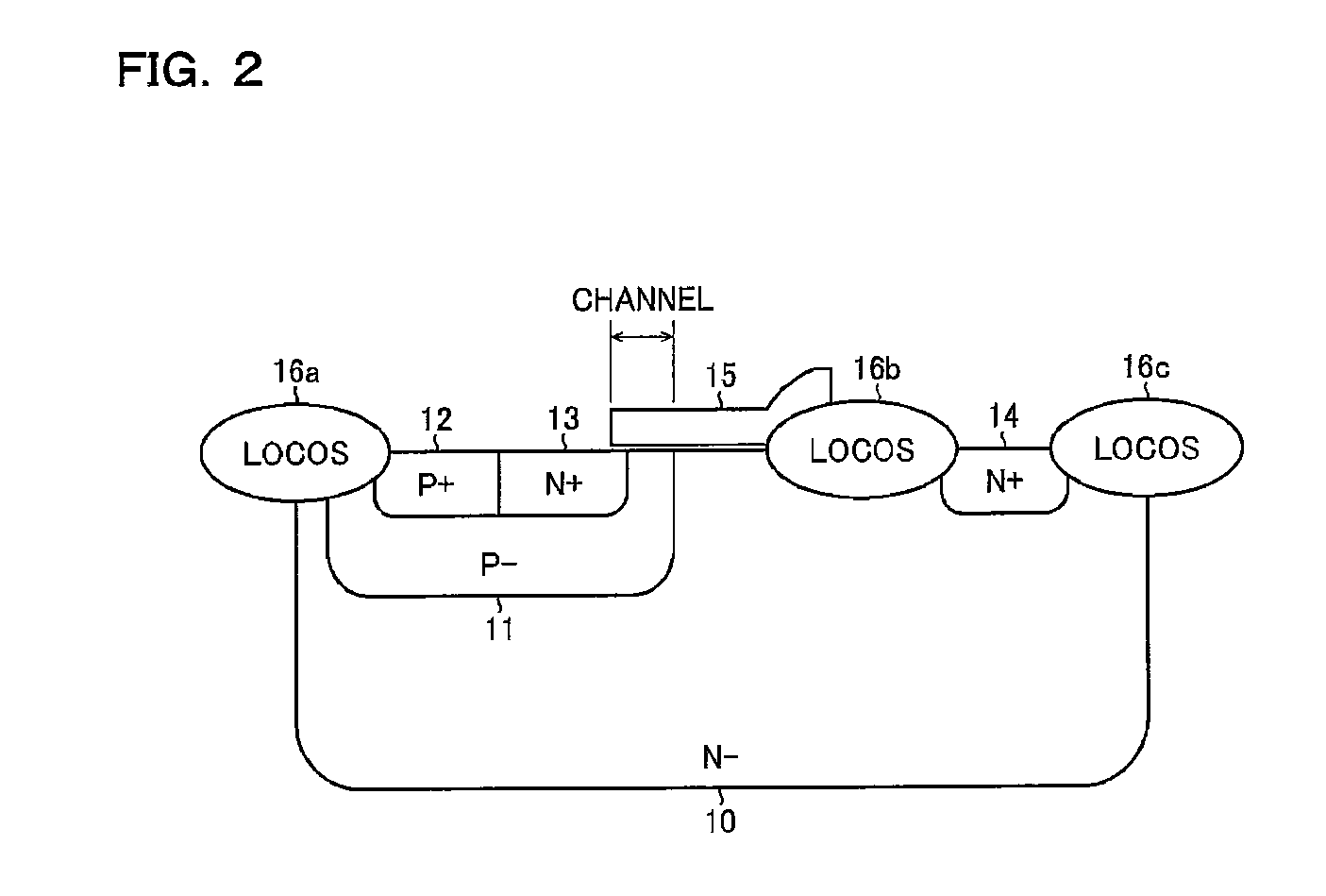
[0044] The semiconductor device 1 is made up of integrated elements including an output power transistor (a N-channel LDMOS transistor) N1, an N-channel LDMOS transistor N2 that is a substitute element of a conventional boot diode (see FIG. 21), a ...
second embodiment
[0093] Next, the step-down chopper regulator according to the present invention will be described in detail.
[0094]FIG. 10 is a block diagram showing a second embodiment of the step-down chopper regulator according to the present invention.
[0095] Note that the step-down chopper regulator of the present embodiment has substantially the same structure as the first embodiment described above. Therefore, parts similar to the first embodiment are denoted by the same reference signs as those in FIG. 1 so that the descriptions thereof will be omitted. Only the characteristic portions of the present embodiment will be described mainly in the following explanation.
[0096] As shown in FIG. 10, the semiconductor device 1 of the step-down chopper regulator in the present embodiment includes a second constant voltage circuit REG2 that generates a second constant voltage Vs2 (here, the gate withstand voltage of the LDMOS transistor N2) that is higher than the constant voltage Vs from the input vo...
third embodiment
[0106] Next, the step-down chopper regulator according to the present invention will be described in detail.
[0107]FIG. 12 is a diagram showing a third embodiment of the step-down chopper regulator according to the present invention.
[0108] Note that the step-down chopper regulator of the present embodiment has a structure that is substantially the same as that in the first embodiment. Therefore, parts similar to the first embodiment are denoted by the same reference signs as those in FIG. 1 so that the descriptions thereof will be omitted. Only the characteristic portions of the present embodiment will be described mainly in the following explanation.
[0109] Adding to the structural elements in the first embodiment, the semiconductor device 1 further includes a continuous pulse driving transistor (an N-type LDMOS transistor) N3, a continuous pulse portion control circuit (a second logic generating circuit) CTRL3 and a continuous pulse portion drive circuit (a second drive circuit) D...
PUM
 Abstract
Description
Claims
Application Information
 - R&D
- Intellectual Property
- Life Sciences
- Materials
- Tech Scout
- Unparalleled Data Quality
- Higher Quality Content
- 60% Fewer Hallucinations
Browse by: Latest US Patents, China's latest patents, Technical Efficacy Thesaurus, Application Domain, Technology Topic, Popular Technical Reports.
© 2025 PatSnap. All rights reserved.Legal|Privacy policy|Modern Slavery Act Transparency Statement|Sitemap|About US| Contact US: help@patsnap.com


