Partial pre-mix flare burner and method

a technology of pre-mixed flares and burners, which is applied in the direction of incinerator equipment, lighting and heating equipment, combustion types, etc., can solve the problems of difficult to increase the flow rate of fuel to support a larger capacity, the enclosure can be costly to erect and maintain, and the need for large volume of fuel to be combusted, etc., to achieve short flame envelopes, reduce the length of flame envelopes, and increase the volume of fuel

Inactive Publication Date: 2008-04-03
JOHN ZINK CO LLC
View PDF41 Cites 19 Cited by
  • Summary
  • Abstract
  • Description
  • Claims
  • Application Information

AI Technical Summary

Benefits of technology

[0010]In accordance with the invention, a flare burner is provided that is capable of combusting a high volume of fuel with a relatively short flame envelope. The decrease in the length of the flame envelope leads to many advantages. For example, the height of the surrounding enclosure of a ground flare can be decreased or the volume of the fuel that can be flared with an existing enclosure height can be increased.

Problems solved by technology

On the other hand, such flares need to have the capacity to combust a large volume of fuel at any given time.
As a result, the enclosure can be costly to erect and maintain.
Unfortunately, due to the interaction of the individual fuel jets, the dense core of fuel formed at the center of the flame envelope makes it difficult to increase the flow rate of the fuel to support a larger capacity without causing the length of the flame envelope to increase and / or smoke to occur.
An increase in the length of the flame envelope often requires the enclosure surrounding the ground flare to be higher which can significantly increase the cost of the enclosure.

Method used


Image

  • Partial pre-mix flare burner and method
  • Partial pre-mix flare burner and method
  • Partial pre-mix flare burner and method

Examples


example 1

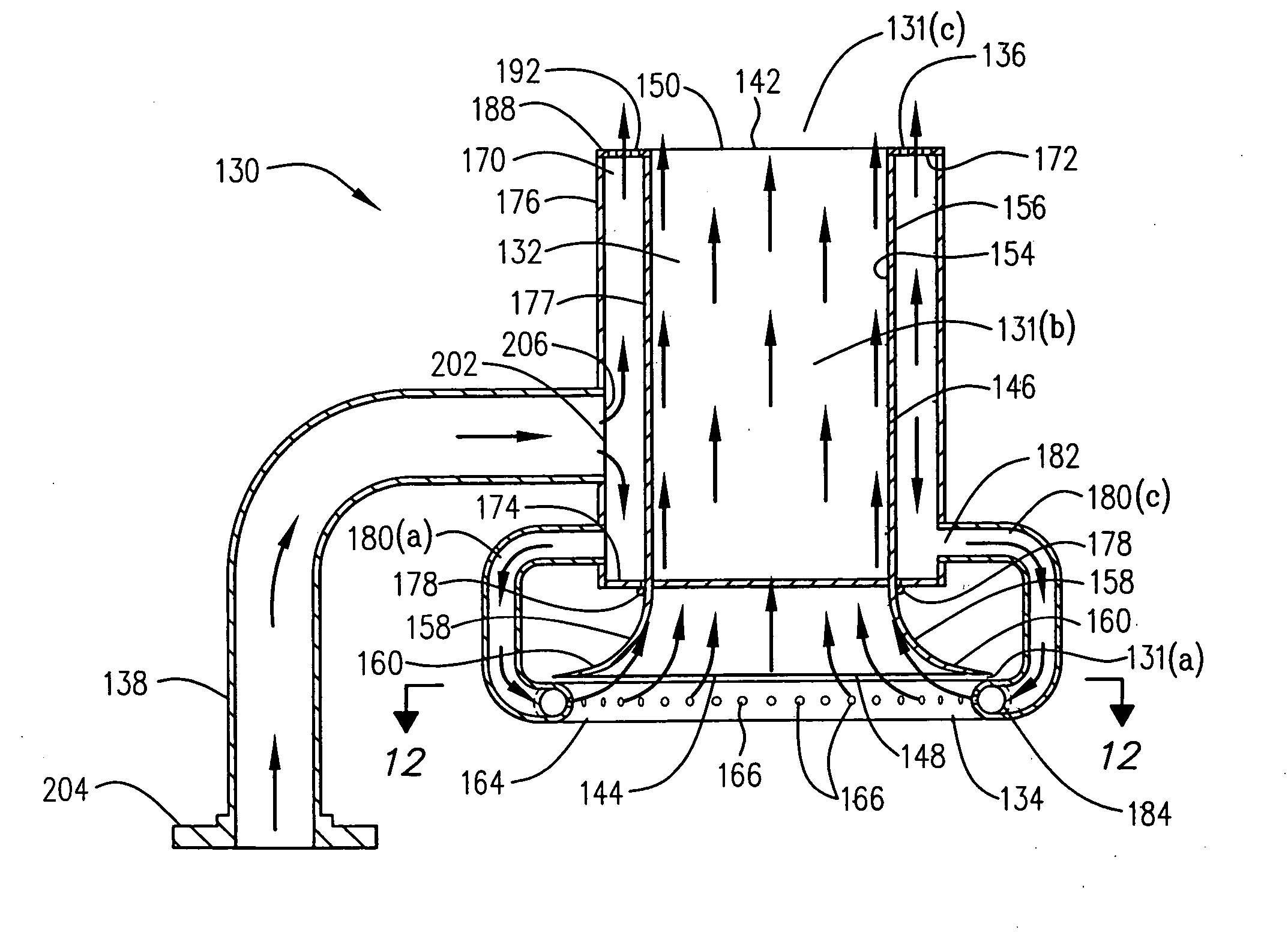
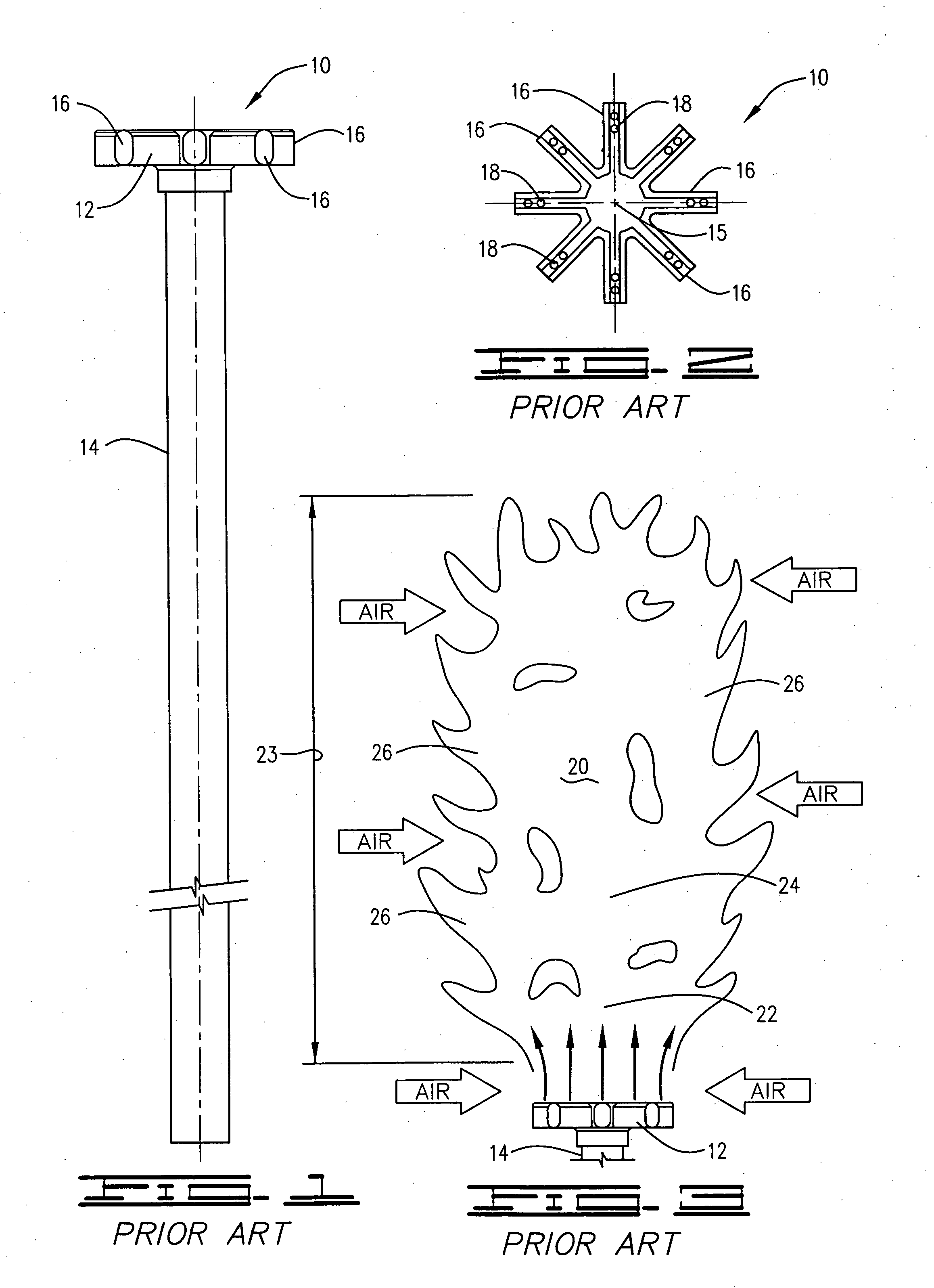
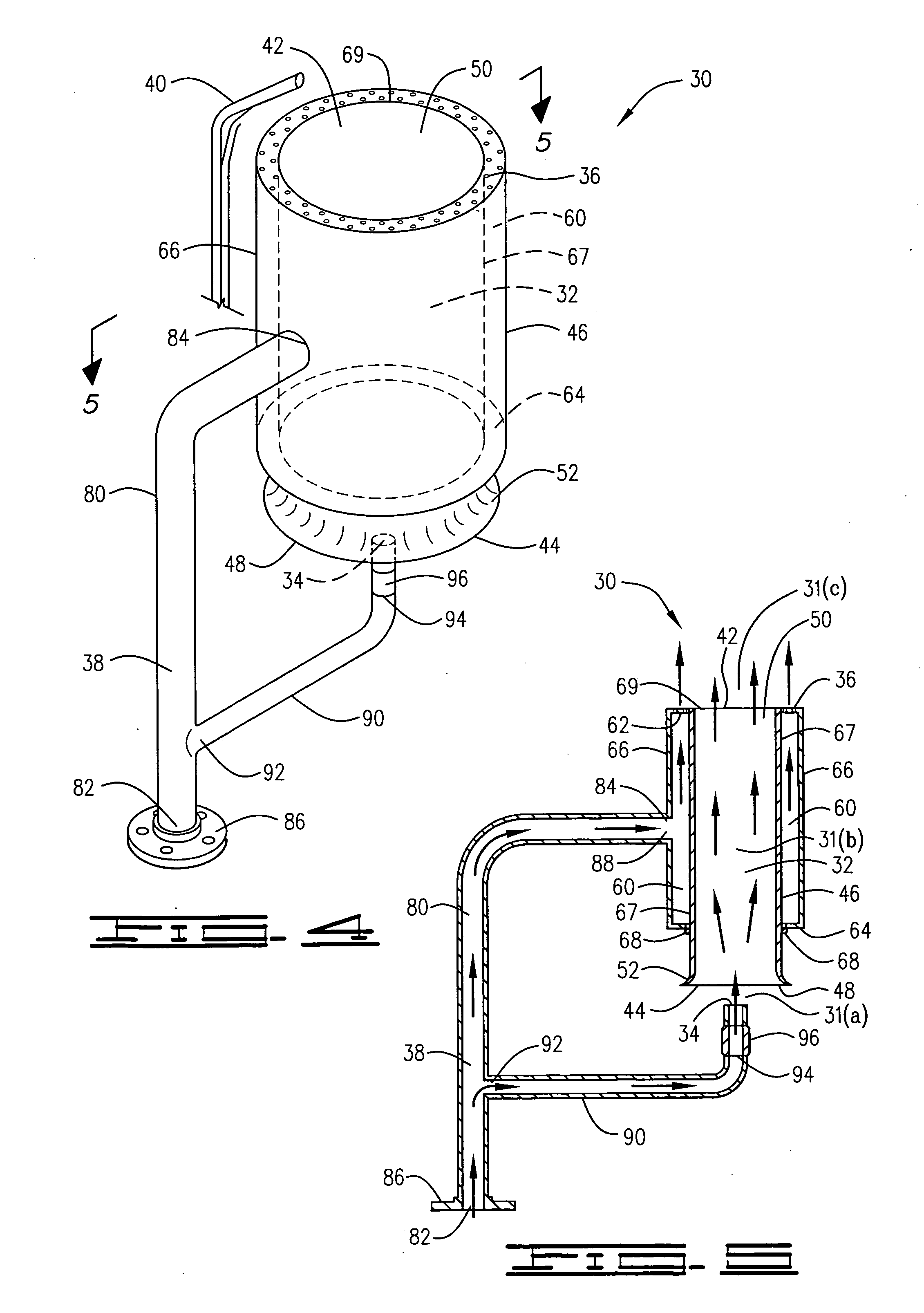
[0152]The first embodiment of the inventive flare burner, flare burner 30, was compared to a prior art high capacity diffusion-type ground flare burner, namely the burner illustrated in FIGS. 1 and 2. Two of the inventive flare burners were tested, one approximately 30 inches in length and the other approximately 16 inches in length. The inventive flare burners were ported to match the three square inches of flow area contained in the prior art flare burner.

[0153]The inventive flare burners were first tested singularly. Tests were carried out using propane and propylene. Approximately 20% of the fuel was injected into the pre-mix chamber of each of the inventive flare burners. The remaining fuel was then injected around the perimeter of the air / fuel mixture discharged from the pre-mix chamber. It was determined that with both types of fuels, each of the inventive flare burners were able to support a significant flow of fuel while developing a smokeless flame. The flame envelope from...

example ii

[0156]The third embodiment of the inventive flare burner, flare burner 230, was also tested and compared to the prior art flare burner discussed above. The performance of this embodiment of the inventive flare burner appeared to be at least equivalent to the prior art burner. However, the inventive burner produced more smoke at low pressure than the first embodiment of the inventive flare burner described in Example I. The range of smokeless operation was comparative to the smokeless performance of the prior art flare burner.

[0157]In this test, the corners of the pre-mix chamber of the inventive flare burner created complex flow patterns which visually appeared to inhibit the mixing regimen in the pre-mix chamber to some extent. As a result, spurious stratified fuel rich zones were observed to form at the corners of the pre-mix discharge area, resulting in visible smoke strata observed throughout the surface of the flame zone. On the other hand, the inventive flare burner tested was...


PUM


Abstract

A flare burner that is particularly suitable for use in connection with ground flares and other types of flares in which it is important to control the height of the flame envelope created by the burner is provided. The flare burner includes a pre-mix zone including a pre-mix chamber into which air is entrained. A uniform mixture of fuel and air is formed in the pre-mix zone and caused to exit an air/fuel outlet in the top of the pre-mix chamber. In one embodiment, the amount of air in the fuel/air mixture that exits the air/fuel outlet is in excess of the stoichiometric amount of air required to support combustion of the fuel in the mixture. Fuel is injected around the perimeter of the air/fuel outlet, combustion is initiated and a flame envelope is created. By injecting a mixture of fuel and air that includes excess air into the center of the flame envelope, combustion of the central portion of the flame envelope is accelerated which allows more fuel to be flared with a given flame envelope height. The invention also includes a ground flare and a method of flaring fuel with a flare burner.

Description

BACKGROUND OF THE INVENTION[0001]The present invention relates to flare apparatus and methods of flaring flammable waste gases and diverted fuel stock. In one embodiment, the invention relates to ground flare burners, ground flares and associated methods.[0002]Flare apparatus and methods are utilized to burn and dispose flammable waste gases and diverted fuel stock in a variety of applications. For example, flares are typically located at production facilities, refineries, processing plants and the like for disposing of flammable waste gases that are dumped and / or fuel stock streams that are diverted during venting, shut-downs, upsets or emergencies. The flaring of flammable waste gases and diverted fuel stock (hereinafter referred to as “fuel”) without producing smoke is usually desirable or even mandatory. Smokeless flaring is accomplished by assuring that non-oxidized soot does not form in a sufficient quantity to leave the flame. This is accomplished by assuring that a sufficien...

Claims


Application Information

Patent Timeline
Patent Type & Authority Applications(United States)
IPC IPC(8): F23G7/08
CPCF23G7/08F23D14/02F23G7/06
Inventor POE, ROGER L.WILKINS, JAMESWHITE, JEFF W.
Owner JOHN ZINK CO LLC
Why Eureka
Try Eureka