Slit lamp microscope and ophthalmic laser treatment apparatus with the microscope

Inactive Publication Date: 2008-04-03
NIDEK CO LTD
View PDF7 Cites 10 Cited by
  • Summary
  • Abstract
  • Description
  • Claims
  • Application Information

AI Technical Summary

Benefits of technology

[0006]The present invention has an object to provide a slit lamp microscope with a mechanism for changing an observation viewing angle while restraining extension of a working distance and providing an advantage in cost, and a an ophthalmic laser treatment apparatus provided with the slit lamp.

Problems solved by technology

If the working distance is long, therefore, some operators who have short arms may not stably hold the contact lens in contact with a patient's eye while observing the patient's eye.
Further, the mechanical part of the stereo-variator in Patent document 2 is large in size and needs a rotating mechanism for largely changing the viewing angle, leading to a high cost.

Method used


Image

  • Slit lamp microscope and ophthalmic laser treatment apparatus with the microscope
  • Slit lamp microscope and ophthalmic laser treatment apparatus with the microscope
  • Slit lamp microscope and ophthalmic laser treatment apparatus with the microscope

Examples


Embodiment Construction

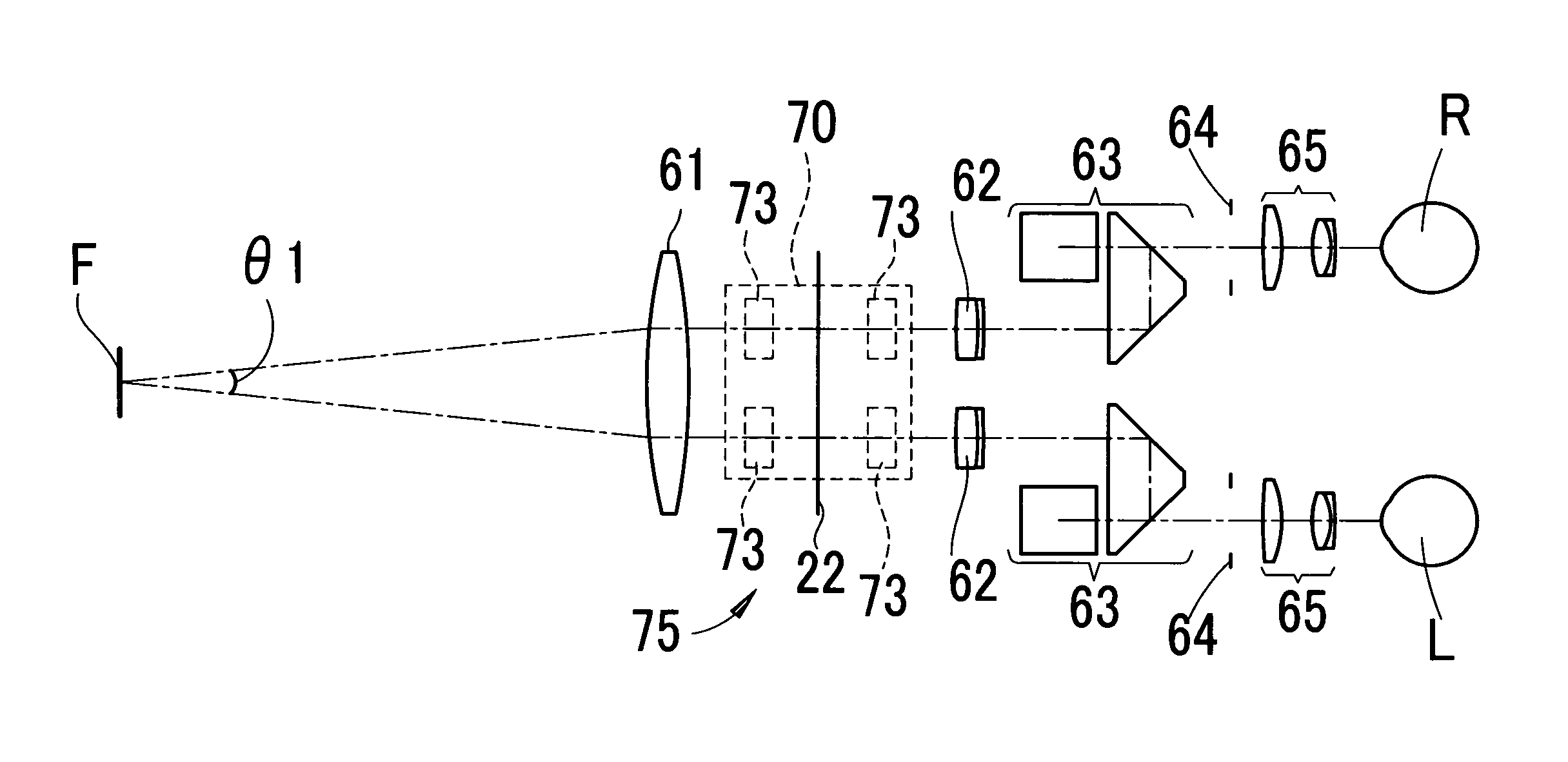
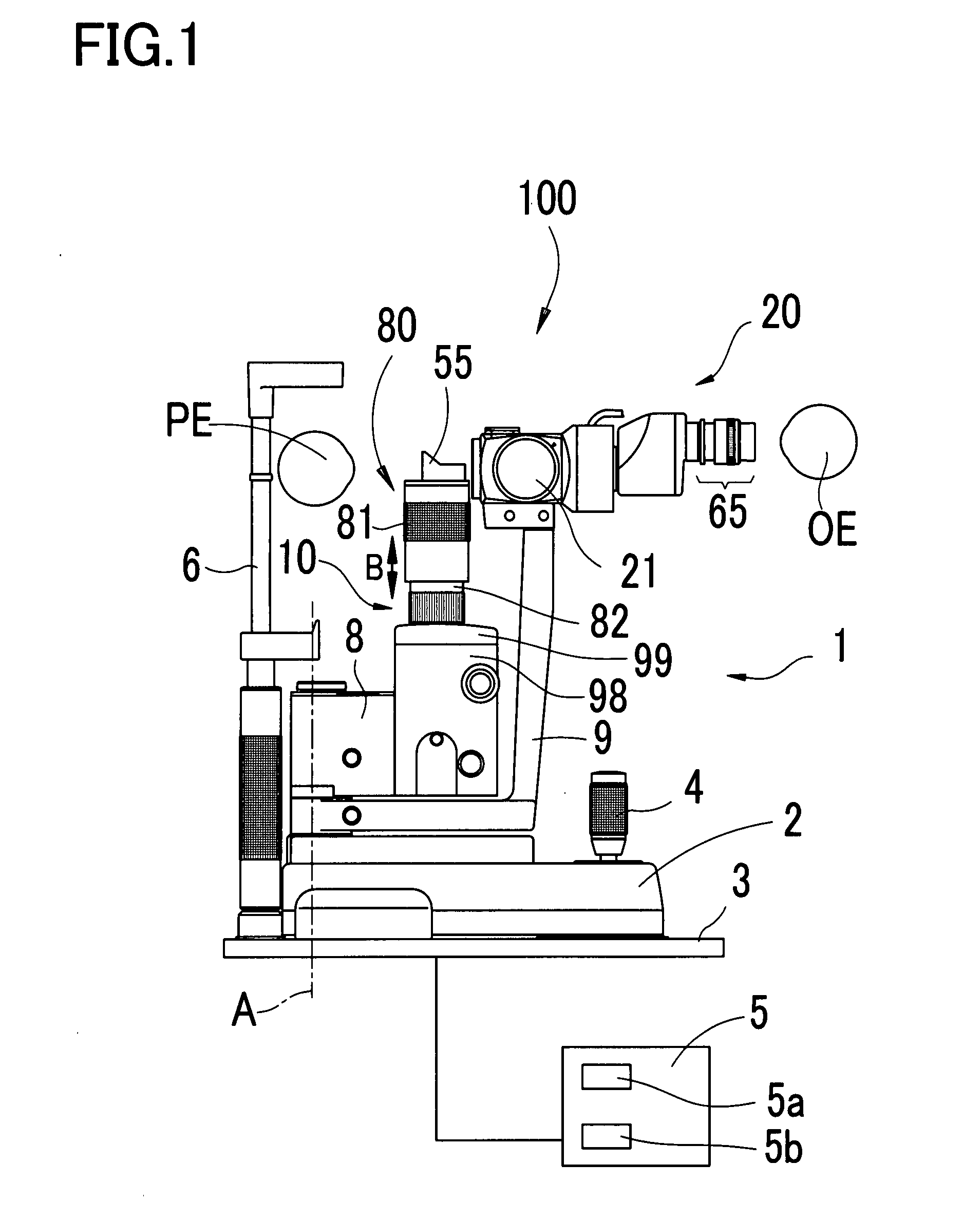
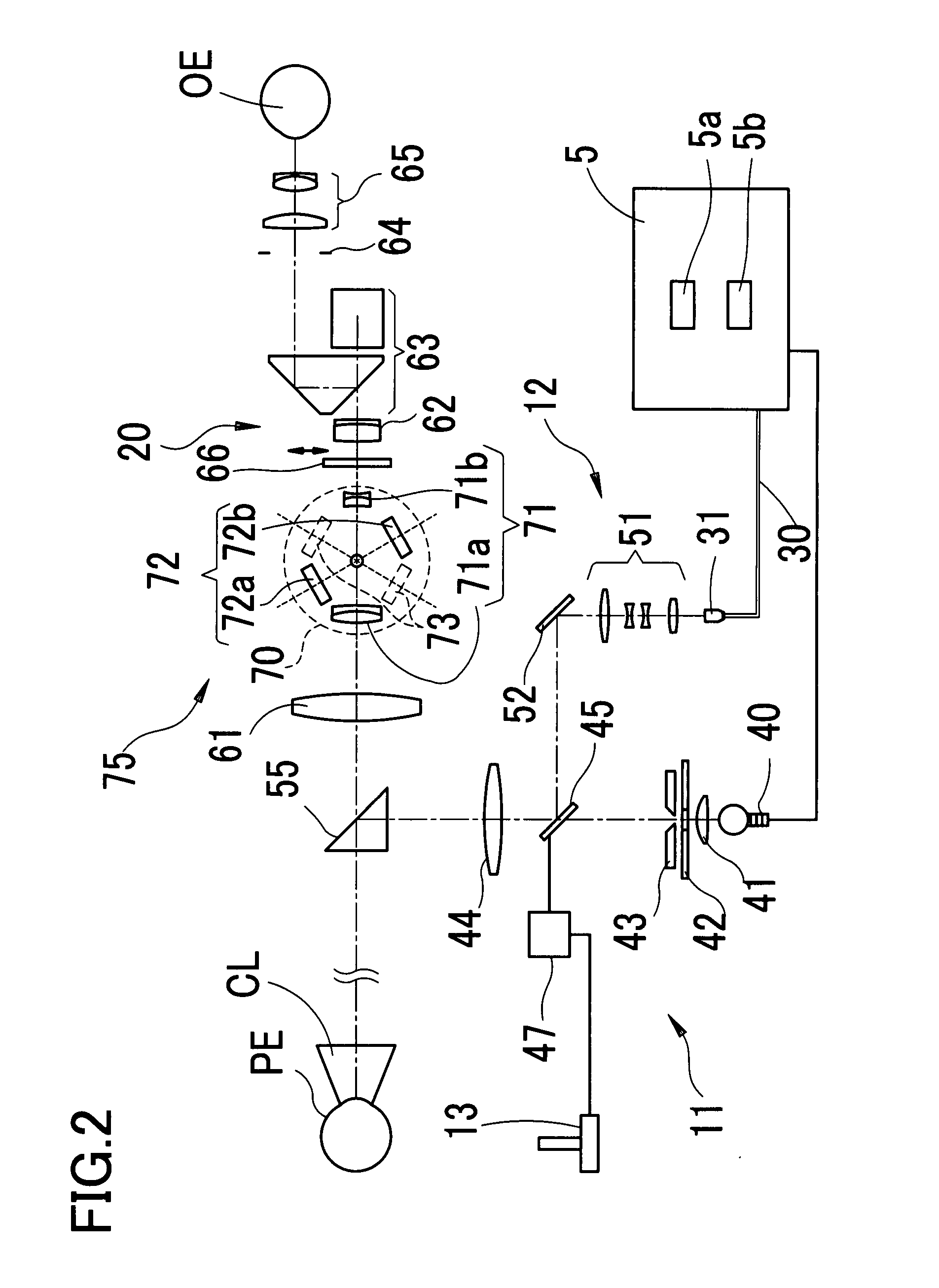
[0020]A detailed description of a preferred embodiment of the present invention will now be given referring to the accompanying drawings. FIG. 1 is a side view of a slit lamp and an ophthalmic laser treatment apparatus provided with the slit lamp in the present embodiment. FIG. 2 is a schematic diagram showing a configuration of the ophthalmic laser treatment apparatus.

[0021]In the present embodiment, the ophthalmic laser treatment apparatus 100 is a photocoagulation apparatus. The slit lamp 1 is used for observation or others of a patient's eye PE. The slit lamp 1 has a base 2 as a lower part, which is mounted on a table 3. Further, the base 2 is movable in a horizontal direction relative to the table 3 by operation of a joystick 4. An operator (an observer) can roughly and finely move the base 2 relative to the table 3 by operating the joystick 4. A headrest 6 having a chinrest, a forehead rest, and others is attached to the table 3 for supporting the head of the patient in a stat...


PUM


Abstract

A binocular slit lamp microscope for observing a patient's eye, comprises: an objective lens; binocular eyepieces; and a mechanism that includes a plurality of optical systems and is arranged to switch the optical systems to be selectively placed in a predetermined position between the objective lens and the binocular eyepieces on an observation optical path, the mechanism including a variable magnification optical system for changing observation magnification and a viewing angle changing optical system for changing a viewing angle between a right viewing path and a left viewing path.

Description

BACKGROUND OF THE INVENTION[0001]1. Field of the Invention[0002]The present invention relates to a slit lamp microscope for observing a patient's eye (an examinee's eye) while irradiating a treatment laser beam to the patient's eye, and an ophthalmic laser treatment apparatus provided with the slit lamp microscope.[0003]2. Description of Related Art[0004]In an ophthalmic laser treatment apparatus arranged to irradiate a treatment laser beam (a laser beam for photocoagulation) to a patient's eye, particularly, a fundus of the eye, a binocular slit lamp microscope is used for observation. As such a slit lamp microscope, there is a configuration that comprises a variable magnification mechanism including a rotating drum with a variable magnification optical system placed within a binocular observation optical system for changing observation magnification (power) by rotating the rotating drum (see for example JP2002-224036A, hereinafter referred to as “Patent document 1”). Besides, ther...

Claims


Application Information

Patent Timeline
IPC IPC(8): A61B3/135
CPCA61B3/135A61F9/008A61F2009/00872A61F2009/00863A61F9/00821
Inventor NAKAMURA, HIROKAZU
Owner NIDEK CO LTD
Why Eureka
Try Eureka