Eureka AIR delivers breakthrough ideas for toughest innovation challenges, trusted by R&D personnel around the world.

Inkjet recording apparatus

a recording apparatus and inkjet technology, applied in the direction of printing, other printing apparatus, etc., can solve the problems of inability to satisfactorily compress the ink, deterioration of the ejection property, printing failure, etc., and achieve the effect of stable drawing a good-quality image for a long period of tim

Inactive Publication Date: 2008-04-03
FUJIFILM CORP
View PDF11 Cites 32 Cited by
  • Summary
  • Abstract
  • Description
  • Claims
  • Application Information

AI Technical Summary

Benefits of technology

The present invention provides an inkjet recording apparatus that can effectively degas and perform stable inkjet ejection for a long period of time. This is achieved by using a high boiling point substance as the ink, and a degassing mechanism that includes a vacuum pump and a reservoir for the ink. The minimum boiling point of the compounds in the ink is approximately 190°C, and the degassing vacuum degree of the degassing mechanism is approximately 0.02 atm. The control interface of the apparatus includes a table that relates the minimum boiling point to the degassing vacuum degree, and a pressure controller that adjusts the degassing vacuum degree to match the target value. The invention is particularly useful for ultraviolet-curable materials.

Problems solved by technology

However, when an air bubble or dissolved gas is present in the inkjet ink, the ink cannot be satisfactorily compressed at the ejection and this gives rise to a problem of deterioration in the ejection property, incapability of generating stable ink drops, occurrence of dot missing or printing failure, or reduction in the reliability of the inkjet recording method.
Therefore, degassing to a high vacuum of 0.1 atm or less (for example, 0.06 atm or less) is substantially impossible.
On the other hand, the gas component in the ink grows by rectified diffusion and particularly when the ejection is continuously performed for a long period of time, the conventional degassing to about 0.1 atm cannot stop growth of the bubble and allows for occurrence of an ejection failure and thus, this is insufficient.
There has been no means effective for stably performing the inkjet ejection for a long period of time.

Method used


Image

  • Inkjet recording apparatus
  • Inkjet recording apparatus
  • Inkjet recording apparatus

Examples


embodiment 1

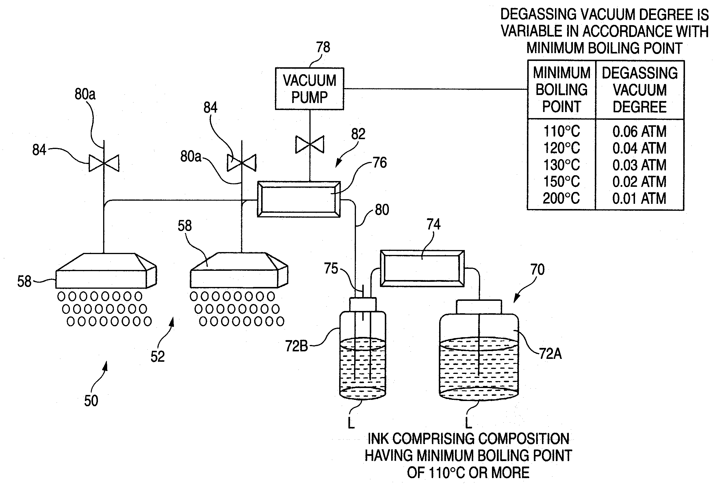
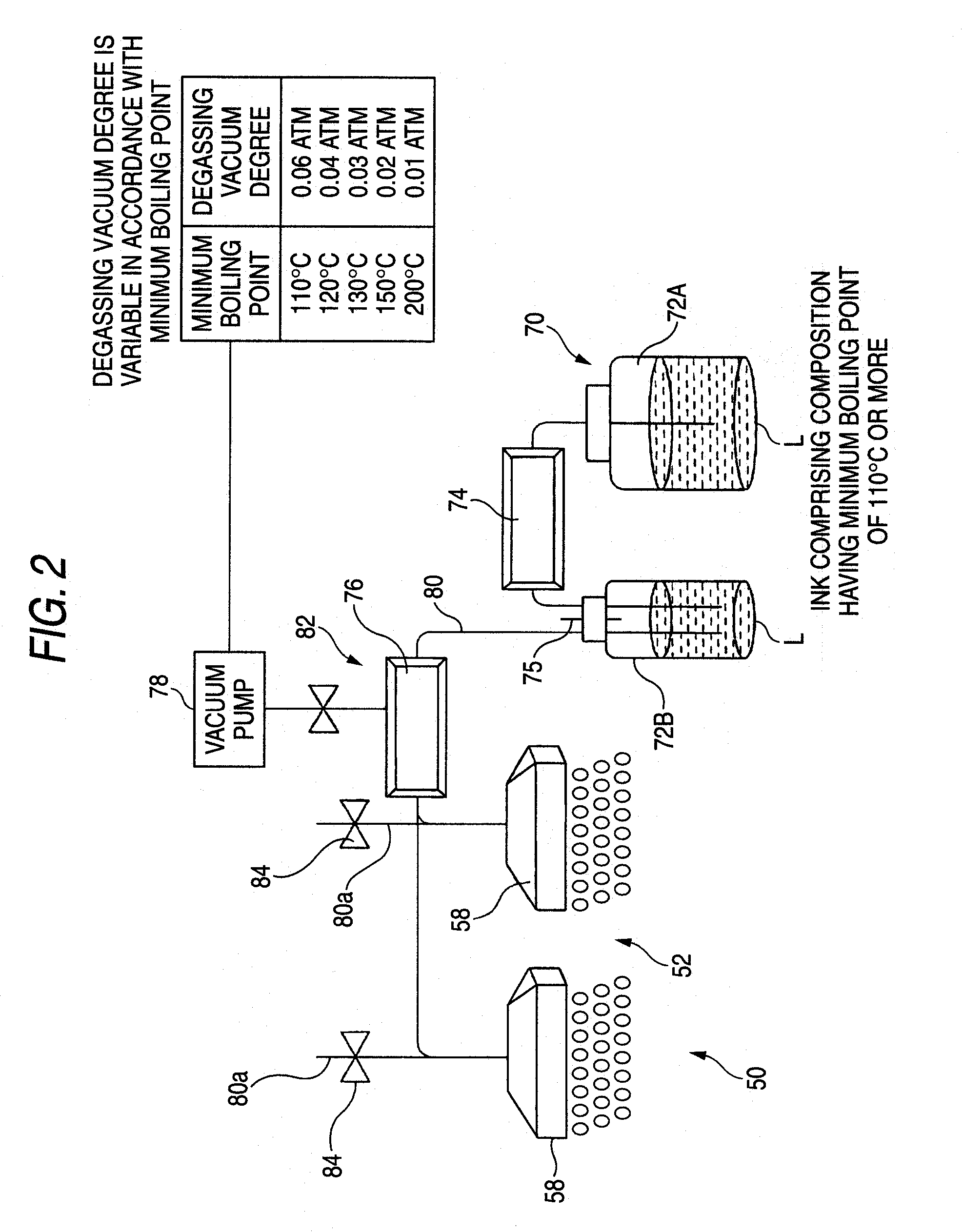
[0026]FIG. 1 is a construction view of an active energy curing-type inkjet recording apparatus as an objective of the present invention, and FIG. 2 is a schematic construction view showing the image recording part and the liquid functional material supply part (hereinafter sometimes referred to as an “ink supply part”) of the active energy curing-type inkjet recording apparatus shown in FIG. 1.

[0027] The construction of the active energy curing-type inkjet recording apparatus is described below.

[0028] In FIG. 1, in a casing 12 of the active energy curing-type inkjet recording apparatus 10, there are provided a recording medium housing part 20 in which sheet-like recording mediums S in the same size are stored by piling a plurality of sheets in the inner lower part of the casing 12, a conveying part 30 in which the recording medium S taken out from the housing part 20 is conveyed to the upper position of the housing part 20, a scan-conveying part 40 which is disposed at the upper p...

embodiment 2

[0063]FIG. 3 is a view showing Embodiment 2 of the present invention and the members already shown in FIG. 2 are indicated using the same reference characters as in FIG. 2 by omitting repeated description thereof here. In FIG. 3, a control interface (PC) is used and equipped with a table showing the relationship of the minimum boiling point vs. the degassing vacuum degree. The table showing the relationship of the minimum boiling point vs. the degassing vacuum degree is a table indicating that the degassing vacuum degree is 0.06 atm when the minimum boiling point of the compounds constituting the ink composition is 110° C., 0.04 atm when 120° C., 0.03 atm when 130° C., 0.02 atm when 150° C., and 0.01 atm when 200° C. When the minimum boiling point is not included in the numerical values above, a degassing vacuum degree interpolated based on the nearest minimum boiling points above and below the unincluded minimum boiling point is used. Only by thus inputting the minimum boiling poin...


PUM


Abstract

An inkjet recording apparatus includes: an inkjet head that ejects a liquid functional material toward a recording medium based on image signals; a recording medium conveying unit that conveys the recording medium to a position opposing the inkjet head; a supply path that supplies the liquid functional material to the inkjet head; a reservoir that communicates the supply path, and that reserves the liquid functional material; and a degassing mechanism that is provided in one of the inkjet head, the supply path and the reservoir, and that includes a degassing device and a vacuum pump, wherein the liquid functional material comprises compounds having minimum boiling point of approximately 110° C. or more, and the degassing vacuum degree of the degassing mechanism is approximately 0.06 atm or less.

Description

BACKGROUND OF THE INVENTION [0001] 1. Field of the Invention [0002] The present invention relates to an inkjet apparatus of forming an image by ejecting a liquid functional material on a recording medium by an inkjet head. [0003] 2. Background Art [0004] The inkjet apparatus of ejecting a liquid functional material (hereinafter referred to as an “ink”) on a recording medium by using an inkjet head and thereby performing the image formation is characterized, for example, in that the system is environment-friendly, high-speed recording on various recording mediums can be realized, and a high-resolution image with less blurring can be obtained. Above all, development of an apparatus using an ultraviolet-curable ink is proceeding in view of easy handling of the light source, compactness and the like. [0005] However, when an air bubble or dissolved gas is present in the inkjet ink, the ink cannot be satisfactorily compressed at the ejection and this gives rise to a problem of deteriorati...

Claims


Application Information

Patent Timeline
Patent Type & Authority Applications(United States)
IPC IPC(8): B41J2/19
CPCB41J2/175B41J11/002B41J2/19B41J2/17556B41J11/00214
Inventor HIRATO, KATSUYUKI
Owner FUJIFILM CORP
Why Eureka
Eureka Blog
Learn More