
Door lock system

a door lock and locking system technology, applied in the field of door lock systems, can solve the problems of panic lever undesired failure to return to the facing position, side door cannot be moved and opened, failure to move and open the side door,

Active Publication Date: 2008-04-03
MITSUI KINZOKU ACT
View PDF12 Cites 8 Cited by
  • Summary
  • Abstract
  • Description
  • Claims
  • Application Information

AI Technical Summary

Benefits of technology

[0022]It is an object of the present invention to at least partially solve the problems in the conventional technology.

Problems solved by technology

This means that when the side door is in the closed state, the side door cannot be moved and opened by pulling the outside handle outward of the vehicle.
The door lock system is disadvantageous in that, in the course of the panic lever's moving between the position at which the pressing portion is away from the distal end of the link lever in the radially outward direction with respect to the panic lever shaft and the position at which the pressing portion is near the distal end of the link lever in the same direction, the pressing portion of the panic lever can be moved in the axial direction of the panic lever shaft.
Hence, the panic lever undesirably fails to return to the facing position.
When the door-opening operation is performed on the door lock system in the unlocked state with the panic lever not returned to the facing position, it is possible that the pressing portion of the panic lever fails to press the pressing portion of the ratchet lever, which leads to a failure in moving and opening the side door.

Method used


Image

  • Door lock system
  • Door lock system
  • Door lock system

Examples


Embodiment Construction

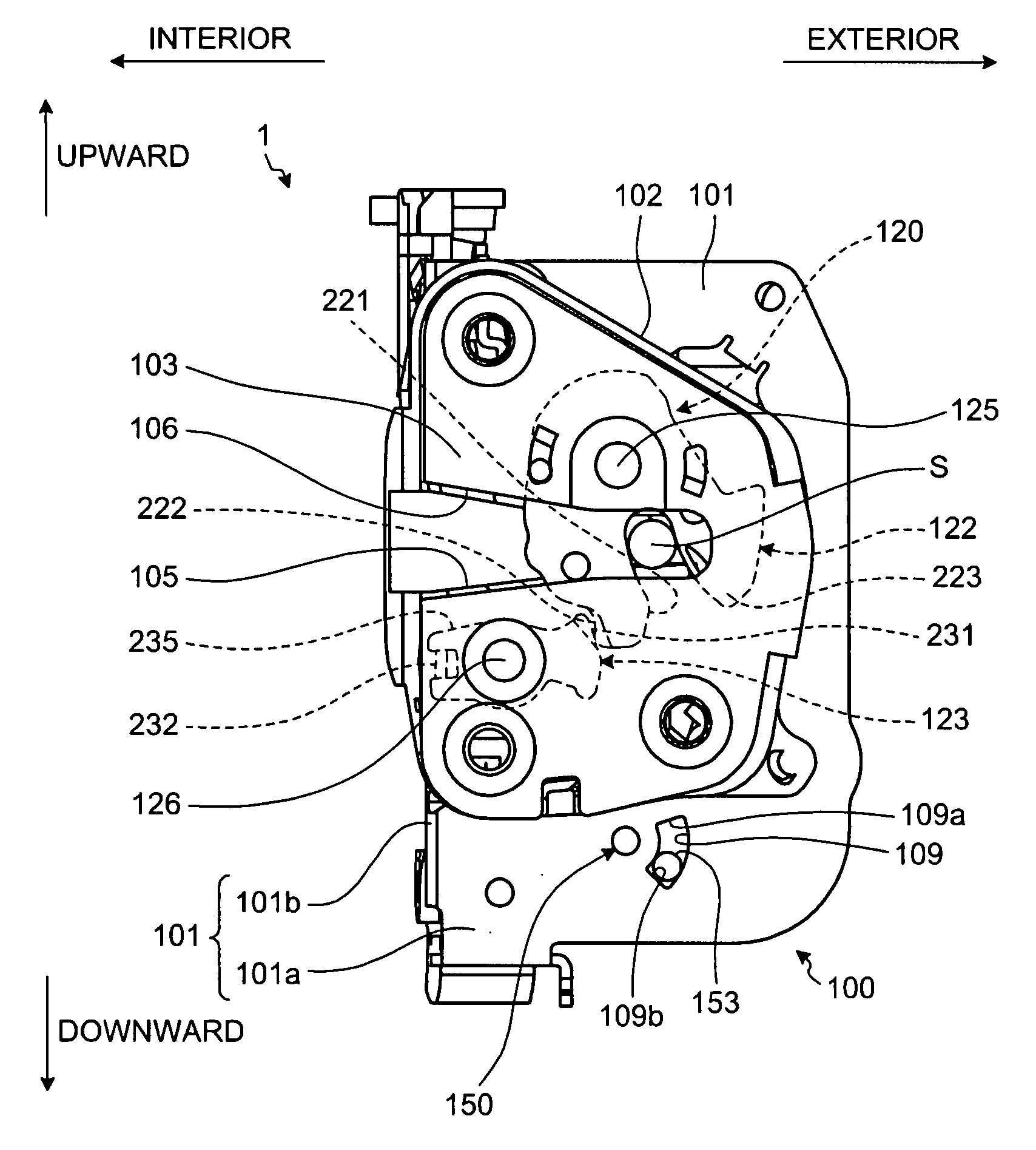
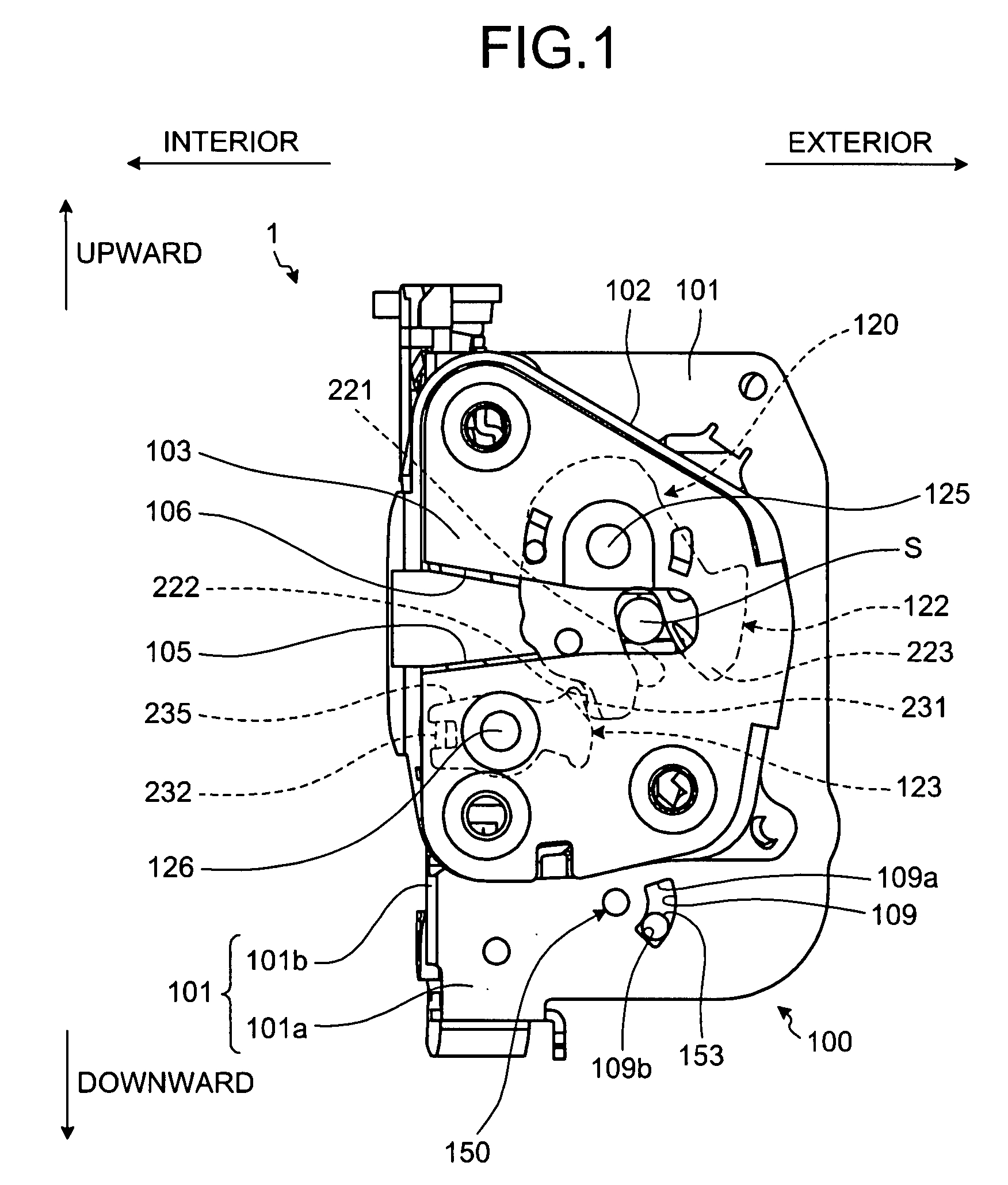
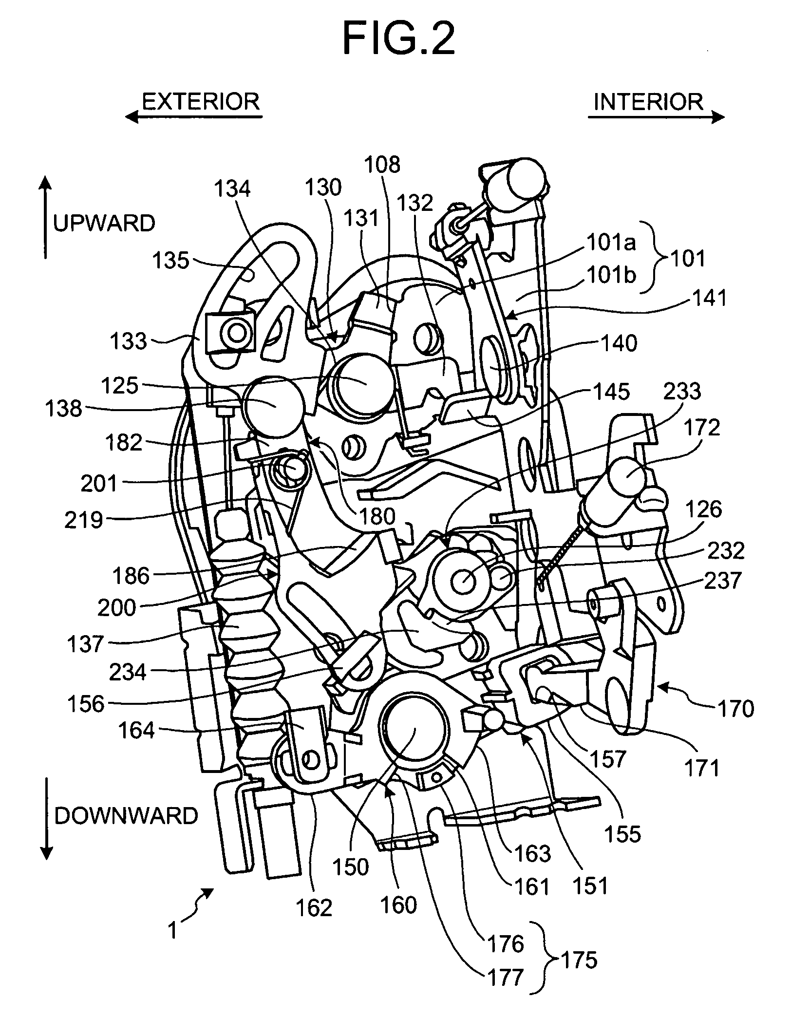
[0058]Exemplary embodiments of a door lock system according to the present invention will be explained below in detail with reference to the accompanying drawings. FIGS. 1 to 5 are diagrams of a door lock system 1 according to the invention. The door lock system 1 taken as an example is for use in a side door D (in a right-hand drive vehicle, the driver's door) which is a front-hinged door provided to the right of a front seat of a four-wheel vehicle as shown in FIG. 6. The door lock system 1 is provided between an outside handle 10 and a latch mechanism 120 shown in FIG. 1.

[0059]The door lock system 1 is switched between a locked state and an unlocked state by locking means. Examples of the locking means include a sill knob 9 shown in FIG. 6 disposed in the cabin of the vehicle, a switch (not shown) at the driver's seat, and a switch (not shown) on a key.

[0060]When the door lock system 1 is switched to the locked state, for instance, an inside handle 12 shown in FIG. 5 and the outs...


PUM


Abstract

A door lock system includes a ratchet, a latch, a ratchet lever that disengages the ratchet from the latch when a disengaging operation is performed, a first link lever that moves to and from a transmitting position and a non-transmitting position, wherein when the first link lever is at the transmitting position, the ratchet lever is allowed to disengage the ratchet from the latch, and when the first link lever is at the non-transmitting position, the ratchet lever is inhibited from disengaging the ratchet from the latch, a second link lever that is pivotally coupled to a base end of the first link lever at a base end of the second link lever and that moves in response to a locking operation and an unlocking operation, and a panic spring that transmits, when the unlocking operation is performed, a motion of the second link lever to the first link lever using a resilient force of the panic spring to move the first link lever to the transmitting position. A distal end of the first link lever and a distal end of the second link lever constantly overlap each other.

Description

BACKGROUND OF THE INVENTION[0001]1. Field of the Invention[0002]The present invention relates to a door lock system for a vehicle.[0003]2. Description of the Related Art[0004]Vehicles such as a four-wheeled vehicle generally include a door lock system between an outside handle and a latch mechanism in a side door.[0005]The latch mechanism includes a latch and a ratchet for engagement. When the side door is closed with respect to a vehicle body, the latch receives a striker provided on the vehicle body in a locking manner, and the ratchet engages with the latch to retain the striker in the locked state so that the side door is held in a closed state with respect to the vehicle body.[0006]The door lock system includes a base plate. A handle lever shaft, a locking lever shaft, and a ratchet lever shaft are disposed on the base plate.[0007]A handle lever is rotatably supported on the handle lever shaft. An outside-handle connecting member is disposed on an end of the handle lever to con...

Claims


Application Information

Patent Timeline
Patent Type & Authority Applications(United States)
IPC IPC(8): E05B65/20E05B83/36E05B77/32E05B79/08
CPCE05B77/32Y10S292/23E05B81/16E05B81/04Y10T292/1082Y10T70/5889Y10T292/1047
Inventor ISHIGURO, KATSUYUKI
Owner MITSUI KINZOKU ACT
Learn More