
Designs for balloon welds

Inactive Publication Date: 2008-03-27
BOSTON SCI SCIMED INC
View PDF59 Cites 15 Cited by
  • Summary
  • Abstract
  • Description
  • Claims
  • Application Information

AI Technical Summary

Benefits of technology

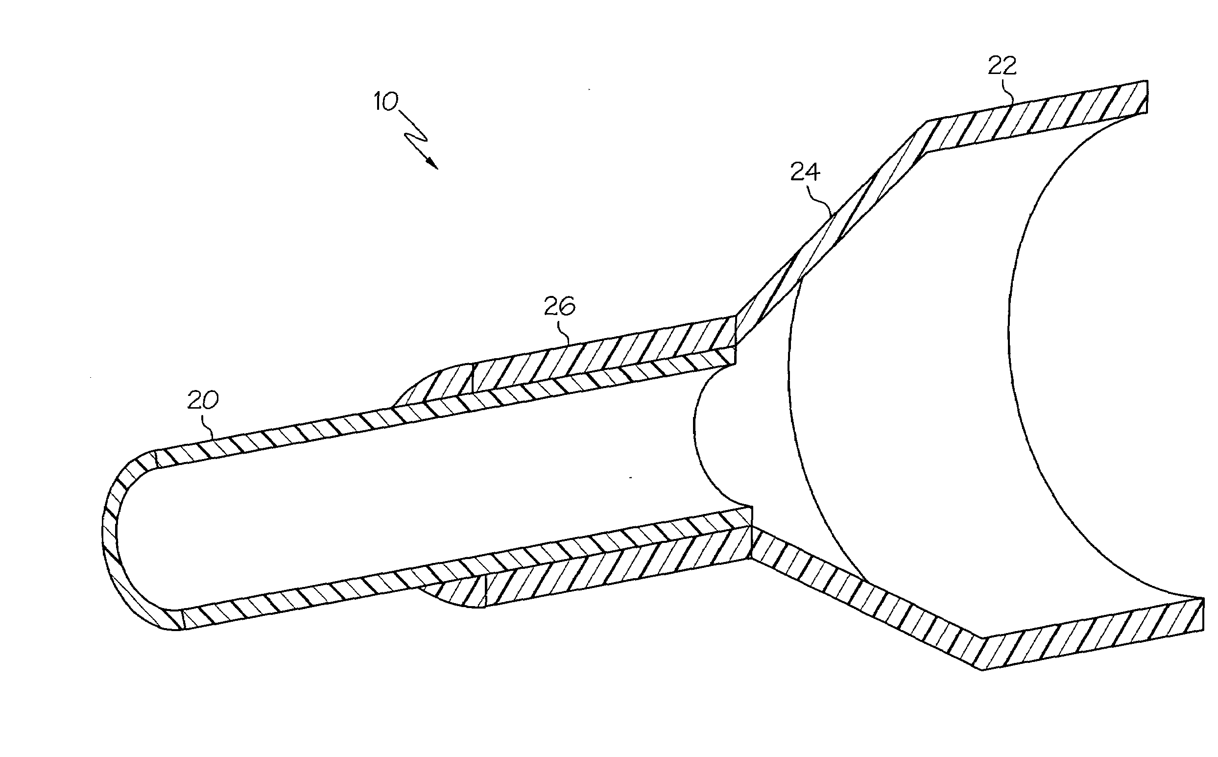
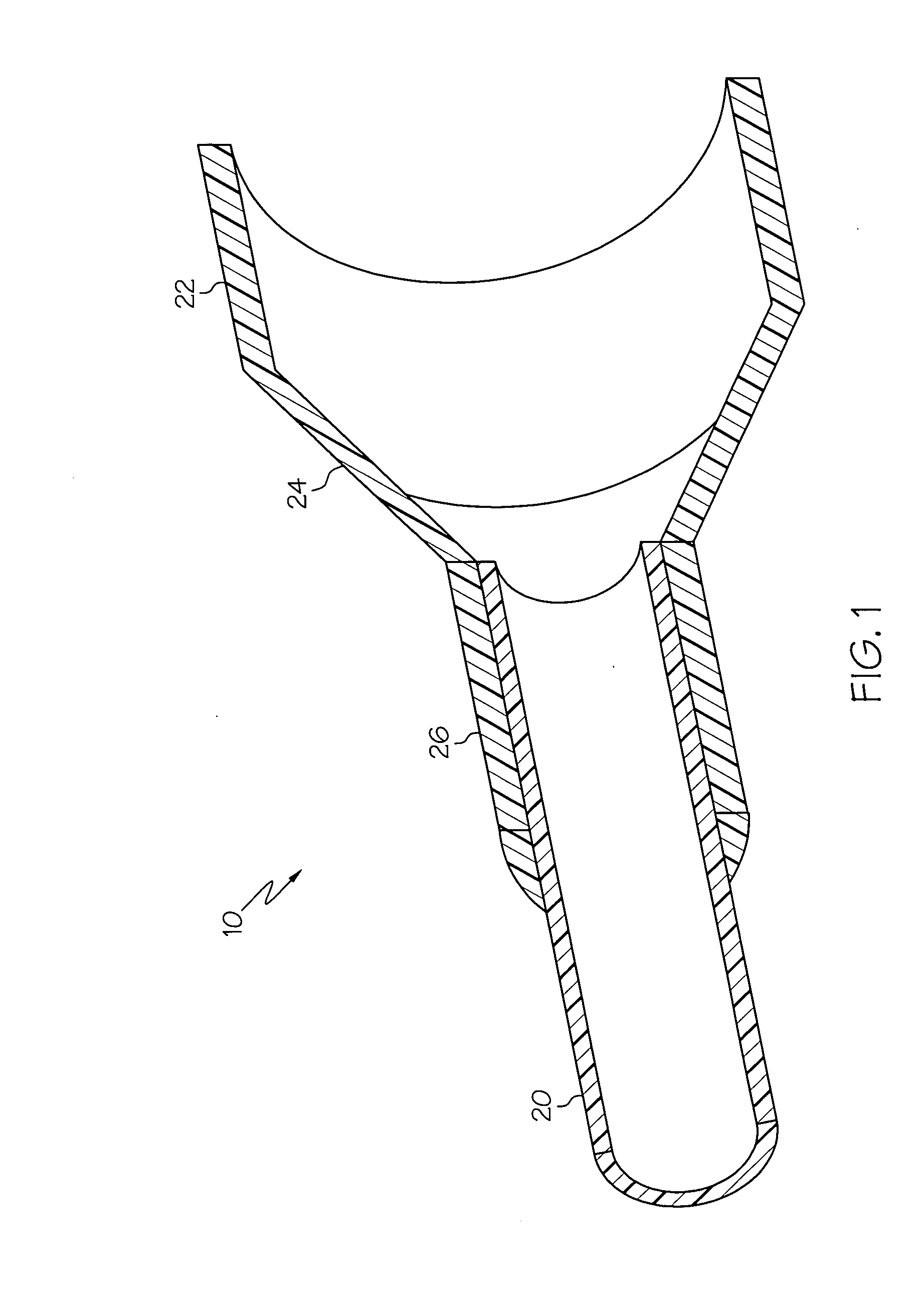
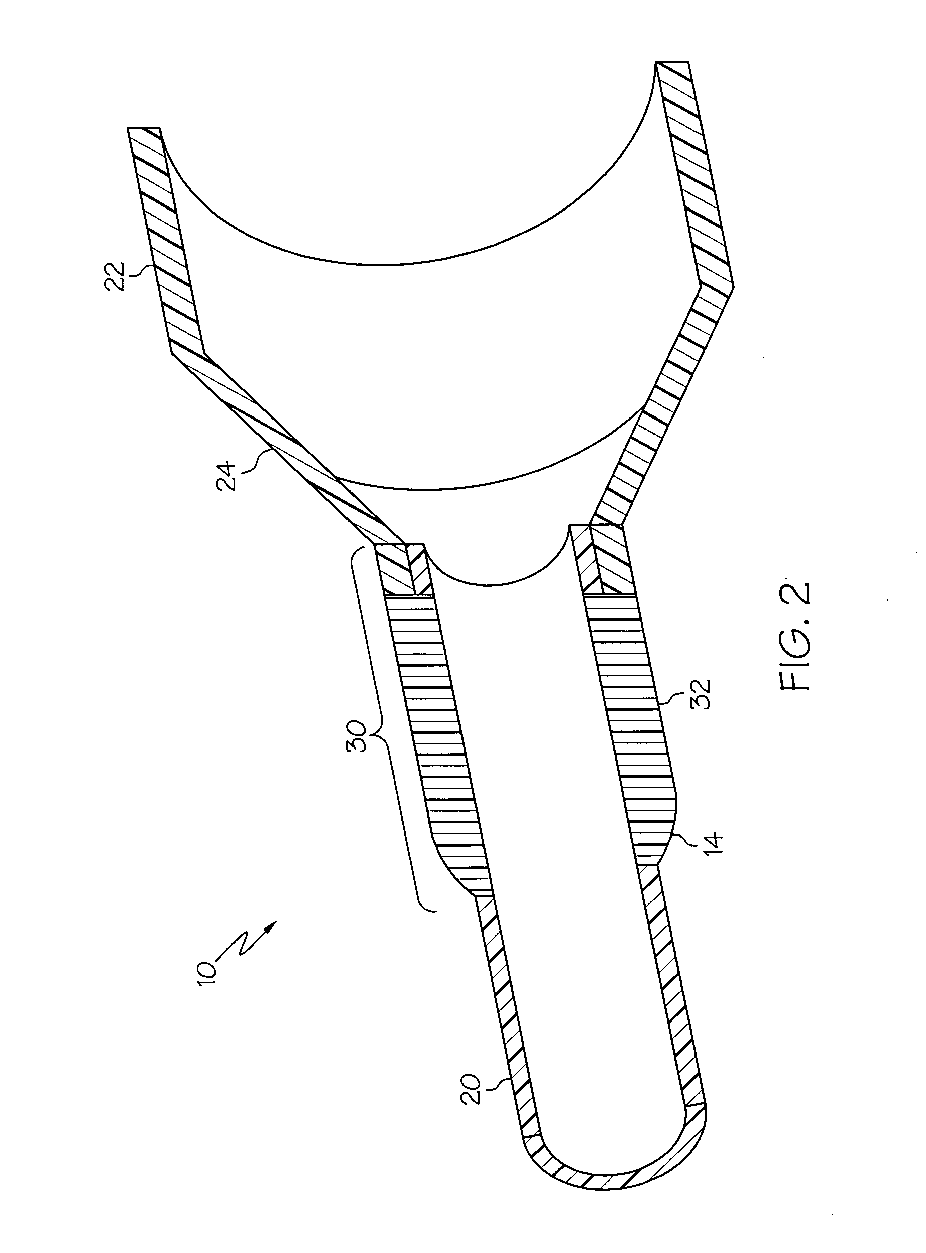
[0010]In order to maintain the flexibility and integrity of the catheter components, embodiments of the present invention are directed to weld geometries, configurations or constructions which minimize the reduction in flexibility caused by welding and methods which minimize the amount of heat required to create the welds so that the integrity of the catheter components are maintained after welding.

Problems solved by technology

A poor seal may result in leakage of inflation fluid and inability to achieve the desired pressure or even rapid loss of pressure and deflation of the balloon.

Method used


Image

  • Designs for balloon welds
  • Designs for balloon welds
  • Designs for balloon welds

Examples


Embodiment Construction

[0022]While this invention may be embodied in many different forms, there are described in detail herein specific embodiments of the invention. This description is an exemplification of the principles of the invention and is not intended to limit the invention to the particular embodiments illustrated.

[0023]For the purposes of this disclosure, like reference numerals in the figures shall refer to like features unless otherwise indicated.

[0024]The invention is directed to weld geometries and methods to produce the inventive weld geometries. Although the figures illustrate the proximal balloon weld, the weld geometries and the methods to produce the inventive weld geometries can be applied to any catheter weld. Thus, it is within the scope of the invention for the weld configurations to be used to engage any two components of a catheter assembly where flexibility of the weld region is to be maintained. Examples of two components of a catheter assembly that may be engaged by the welds ...


PUM

PropertyMeasurementUnit
Temperatureaaaaaaaaaa
Thicknessaaaaaaaaaa
Shrinkageaaaaaaaaaa

Abstract

A catheter assembly comprising a first polymer, a second polymer and a first weld region. The first polymer forms a balloon having a first waist. The second polymer forms a catheter shaft. The first waist is positioned about a portion of the catheter shaft thereby forming the first weld region. The first weld region comprises a first weld and a second weld which engage the first waist to the catheter shaft. The first weld has a first longitudinal position and the second weld has a second longitudinal position, where the first longitudinal position is different from the second longitudinal position.

Description

CROSS-REFERENCE TO RELATED APPLICATIONS[0001]Not ApplicableSTATEMENT REGARDING FEDERALLY SPONSORED RESEARCH[0002]Not ApplicableFIELD OF THE INVENTION[0003]In some embodiments this invention relates to the bonding of components of catheters employed in medical procedures such as angioplasty and stent delivery procedures and more particularly to a weld bonding method and weld geometries.BACKGROUND OF THE INVENTION[0004]Medical catheters having a balloon mounted thereon are useful in a variety of medical procedures. Balloon catheters may be used to widen a vessel into which the catheter is inserted by dilating the blocked vessel, such as in an angioplasty procedure. Balloon catheters may also be used to expand and / or seat a medical device such as a stent or graft at a desired position within a body lumen. In all of these applications, fluid under pressure may be supplied to the balloon through an inflation lumen in the catheter, thereby expanding the balloon.[0005]It is essential in th...

Claims


Application Information

Patent Timeline
IPC IPC(8): A61M29/00A61F2/958
CPCA61M25/1034B29L2031/7543B29C65/04B29C65/1616B29C65/1619B29C65/1674B29C65/168B29C65/1683B29C65/1696B29C65/18B29C65/32B29C65/68B29C66/232B29C66/3462B29C66/534B29C66/63B29C66/65B29C66/652B29C66/91216B29C66/91221B29C66/919B29C66/949B29K2021/003B29K2023/00B29K2023/06B29K2023/0616B29K2023/0625B29K2023/0633B29K2023/065B29K2023/083B29K2027/06B29K2031/04B29K2033/20B29K2067/00B29K2067/006B29K2075/00B29K2077/00B29K2105/0085B29C61/006B29C66/91935B29C66/91921B29C66/961B29C65/3644B29C65/3676B29C65/3684B29C65/1629B29C65/1635B29C65/1654B29C66/91411B29C66/9161B29C66/91655B29C65/16B29L2031/7542B29L2022/022B29C66/73755B29C66/73921B29C66/7394B29C66/73715B29C66/71B29C66/1122B29K2081/04B29K2071/00B29K2067/003B29K2033/08B29K2023/0691B29K2009/06
Inventor FLANAGAN, AIDEN
Owner BOSTON SCI SCIMED INC
Learn More