
Sensor for Measuring a Vibrating Surface Obscured from View

a technology of vibrating surface and sensor, which is applied in the field of vibration measurement, can solve the problems of dampening vibration, damage or destruction of the surface to be measured, and inapplicability of accelerometer measurements and other forms of contact measurements,

Inactive Publication Date: 2008-03-27
MASSACHUSETTS INST OF TECH
View PDF7 Cites 22 Cited by
  • Summary
  • Abstract
  • Description
  • Claims
  • Application Information

AI Technical Summary

Benefits of technology

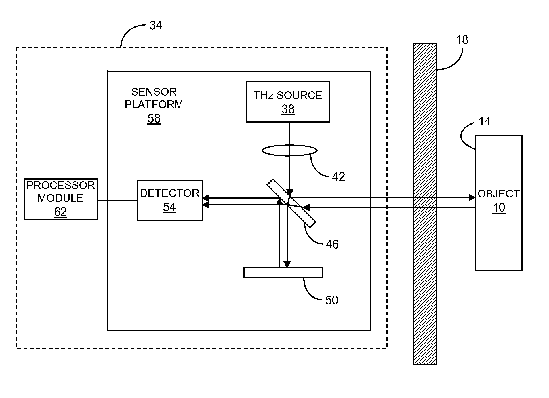
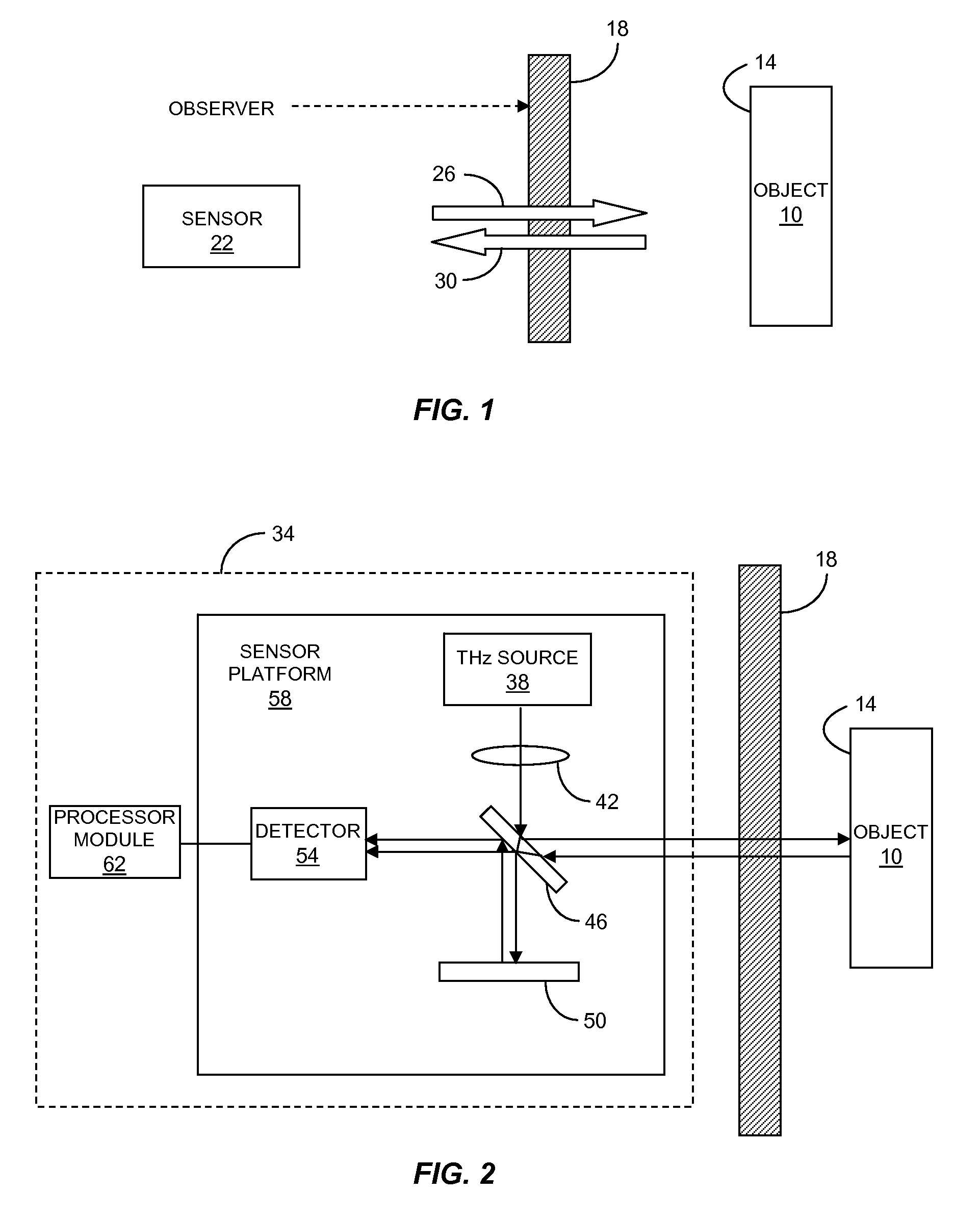
The invention is a sensor that can measure the vibration of a surface using a terahertz beam. The sensor includes a narrowband source of a terahertz beam, a beamsplitter, a beam combiner, a terahertz detector, and a processor module. The sensor can measure the vibration of a surface by measuring the power of the combined sample beam and reference beam, which is responsive to the vibration of the surface. The processor module can produce an electrical signal indicative of the displacement of the surface in response to the measured vibration. The sensor can be used to measure the vibration of a surface that is obscured from view.

Problems solved by technology

In many applications accelerometer measurements and other forms of contact measurements are not practical.
The surface to be measured may be damaged or destroyed if a contact device is attached.
The weight and stiffness of the device may dampen the vibration, and the vibration measurement is limited to the region on the surface where the device is attached.
In addition, contact measurements are not feasible if the surface to be measured is located in an inaccessible space.
Optical vibrometers are often used in applications where physical contact or object location make contact measurements impractical.
These measurements are limited to applications where there is a direct optical path between the vibrometer and the surface.

Method used


Image

  • Sensor for Measuring a Vibrating Surface Obscured from View
  • Sensor for Measuring a Vibrating Surface Obscured from View
  • Sensor for Measuring a Vibrating Surface Obscured from View

Examples


Embodiment Construction

[0022]In brief overview, the invention relates to a sensor for measuring a vibration of a surface obscured from view. The sensor includes a narrowband source of a terahertz beam, a beamsplitter, a beam combiner and a terahertz detector. The beamsplitter splits the terahertz beam into a sample beam for irradiating the surface and a reference beam. The beam combiner combines the sample beam scattered from the surface and the reference beam. The combined beams are received at the terahertz detector which generates an electrical signal based on a modulation of the power of the combined beams in response to the vibrating surface. The electrical signal is indicative of a characteristic of the vibration of the surface. The sensor components can be arranged in a Michelson or a Mach-Zehnder interferometer configuration. The beamsplitter and the beam combiner can be integrated as a single optical element such as the beamsplitter / combiner of a Michelson interferometer.

[0023]Terahertz radiation...


PUM


Abstract

Described are a sensor and a method for measuring a vibration of a surface obscured from view. The sensor includes a narrowband source of a terahertz beam, a beamsplitter, a beam combiner and a terahertz detector. The beamsplitter splits the terahertz beam into a sample beam for irradiating the surface and a reference beam. The beam combiner combines the sample beam scattered from the surface and the reference beam. The terahertz detector generates an electrical signal based on a modulation of the power of the combined beams due to the vibrating surface. The electrical signal indicates a characteristic of the surface vibration. Homodyne or heterodyne detection can be utilized. Advantageously, the sensor can see surfaces that are covered, concealed or otherwise obscured behind optically opaque materials, including plastic, cloth, foam, paper and other materials. Thus the sensor has a wide variety of applications where conventional vibrometers are not practical.

Description

RELATED APPLICATION[0001]This application claims the benefit of the earlier filing date of U.S. Provisional Patent Application Ser. No. 60 / 847,066, filed Sep. 25, 2006, titled “Terahertz Interferometer that Senses Vibration Behind Barriers,” the entirety of which is incorporated herein by reference.GOVERNMENT RIGHTS IN THE INVENTION[0002]This invention was made with United States government support under Contract No. FA8721-05C-0002 awarded by the United States Air Force. The government may have certain rights in the invention.FIELD OF THE INVENTION[0003]The present invention relates generally to the measurement of vibrations. More particularly, the invention relates to sensing a vibrating surface obscured from view using terahertz radiation.BACKGROUND OF THE INVENTION[0004]Measurements of surface vibrations can be made according to a wide variety of techniques. For example, accelerometers can be attached to the surface to be measured to generate an electrical signal responsive to t...

Claims


Application Information

Patent Timeline
Patent Type & Authority Applications(United States)
IPC IPC(8): G01B11/02
CPCG01H9/00G01B15/00
Inventor CHEN, JERRY C.KAUSHIK, SUMANTH
Owner MASSACHUSETTS INST OF TECH
Learn More