Ion beam measuring method and ion implanting apparatus

a technology of ion beam and measuring method, applied in the field of ion beam measuring method, can solve the problems of reducing productivity, increasing cost, and complicated structur

Active Publication Date: 2008-03-27
NISSIN ION EQUIP CO LTD
View PDF4 Cites 3 Cited by
  • Summary
  • Abstract
  • Description
  • Claims
  • Application Information

AI Technical Summary

Benefits of technology

The present invention provides a way to measure different angles and sizes of an ion beam with just one device. This makes it easier than previous methods that required multiple components or configurations.

Problems solved by technology

This patent discusses various ways to improve the precision of controlling the incidence angle of an ion beam during its use in ion implantation processes. One issue addressed is how to accurately control the centering point of the ion beam's movement in relation to thetarget being impacted. Another challenge is finding methods to control the behavior of individual ions within the beam without adding complexity or increasing costs.

Method used


Image

  • Ion beam measuring method and ion implanting apparatus
  • Ion beam measuring method and ion implanting apparatus
  • Ion beam measuring method and ion implanting apparatus

Examples


Embodiment Construction

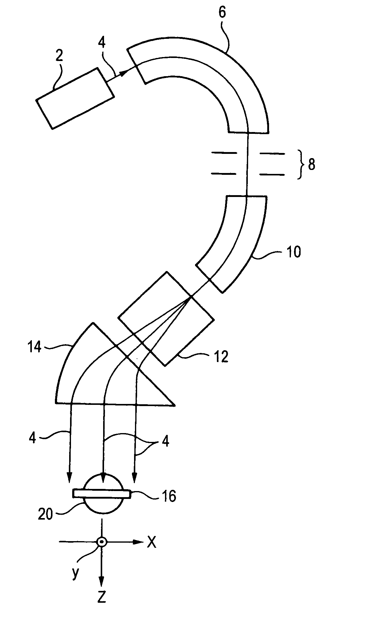
[0073]FIG. 7 is a view showing an essential portion of an embodiment of an ion implanting apparatus for embodying an ion beam measuring method according to the invention. A constitution of a total of the ion implanting apparatus refers to FIG. 1 and the explanation related thereto. Further, portions the same as or corresponding to those in the example shown in FIG. 1 are attached with the same notations and in the following, a difference thereof from those of the above-described example will mainly be explained.

[0074]As described above, the ion beam 4 may be an ion beam which is formed into a ribbon-like shape through scanning in x direction, or that which is formed into a ribbon-like shape not through scanning in x direction. Briefly speaking, in both the cases, the width in x direction is large.

[0075]The ion implanting apparatus includes the forestage multipoints Faraday 24 at a position zff on an upstream side of the target 16 and includes the poststage multipoints Faraday 28 at ...


PUM


Abstract

A change of a beam current of an ion beam which passes an outside of the side of a forestage beam restricting shutter, and which is incident on a forestage multipoints Faraday is measured while the forestage beam restricting shutter is driven in a y direction by a forestage shutter driving apparatus in order to obtain a beam current density distribution in the y direction of the ion beam at a position of the forestage beam restricting shutter. A change of a beam current of the ion beam which passes an outside of the side of a poststage beam restricting shutter, and which is incident on a poststage multipoints Faraday is measured while the poststage beam restricting shutter is driven in the y direction by a poststage shutter driving apparatus in order to obtain a beam current density distribution in the y direction of the ion beam at a position of the poststage beam restricting shutter. By using these results, an angle deviation, a diverging angle, and/or a beam size in the y direction of the ion beam can be obtained.

Description


Claims


Application Information

Patent Timeline
Owner NISSIN ION EQUIP CO LTD
Why Eureka
Try Eureka