Self-boosting friction brake

Active Publication Date: 2008-03-27
ROBERT BOSCH GMBH
View PDF4 Cites 8 Cited by
  • Summary
  • Abstract
  • Description
  • Claims
  • Application Information

AI Technical Summary

Benefits of technology

[0012]The vehicle brake of the invention can as a result be released or put out of operation in every case, including in case of failure. An example of such a failure is if the vehicle brake cannot be released with its actuating device. By disengagement of the fixation device of the vehicle brake of the invention, a vehicle equipped with this vehicle brake can still be moved. A further advantage of the invention is that the vehicle brake can be designed in the self-locking range. At an average coefficient of friction between the friction brake lining and the brake body, this means that the self-boosting is so great that the actuation force is zero. At a higher coefficient of friction, self-locking of the vehicle brake would ensue, unless the actuating device were to prevent an increase in the braking force. In the self-locking range, for releasing the vehicle brake and reducing the braking force, a force oriented counter to the self-boosting action must be exerted by the actuating device. In other words, an actuating force is necessary for release instead of for actuation of the vehicle brake. If the vehicle brake is actuated in the self-locking range, then in case of failure it can be released by disengagement of the fixation device or in any case put out of operation; as a result, locking of a braked vehicle wheel can be averted. The invention thereby makes it possible to design the vehicle brake in the self-locking range, at an average coefficient of friction or even in the entire range of the coefficient of friction. This has the advantage of a low actuation force and actuating energy, which in turn makes a less-powerful and hence lighter-weight and smaller actuating device possible.
[0013]The self-boosting device need not be movable exactly in the direction of rotation of the brake body; it suffices if one component of the direction of motion is in the direction of rotation of the brake body. The self-boosting device may for instance be movable in a chord direction to the brake body. It is essential that as a result of the motion of the self-boosting device, the bracing of the friction brake lining is lost and the braking force is rescinded. It may suffice that part or parts of the self-boosting device are movable, which is what movability of the self-boosting device is to be understood to mean. What is definitive is that the actuated vehicle brake releases independently as a result of the motion of the self-boosting device.

Problems solved by technology

An example of such a failure is if the vehicle brake cannot be released with its actuating device.

Method used


Image

  • Self-boosting friction brake
  • Self-boosting friction brake

Examples


Embodiment Construction

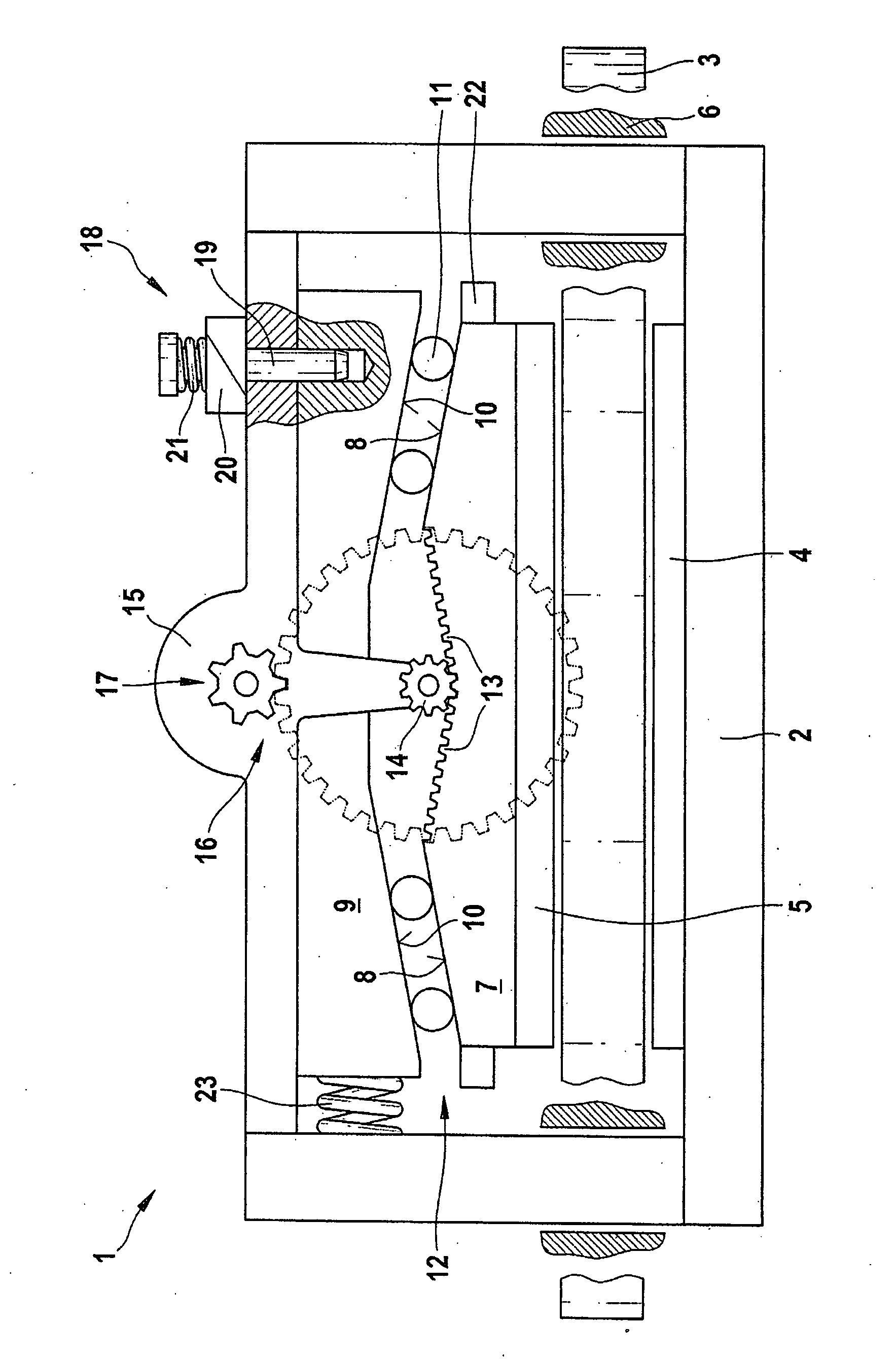
[0015]The vehicle brake of the invention shown in the drawing is embodied as a disk brake I. It has a brake caliper 2, in which on both sides of a brake disk 3 there are respective friction brake linings 4, 5. One of the two friction brake linings 4 is disposed fixedly in the brake caliper 2 and will hereinafter also be called the fixed friction brake lining 4. The other friction brake lining 5 is movable in the brake caliper 2 and will hereinafter also be called the movable friction brake lining 5. The brake caliper 2 is a so-called floating caliper; it is guided displaceably with guides 6 transversely to the brake disk 3. For actuating the disk brake 1, the movable friction brake lining 5 is pressed against the brake disk 3 in a manner to be described hereinafter. In the process, the brake caliper 2 embodied as a floating caliper moves transversely to the brake disk 3 and presses the fixed friction brake lining 4 against the other side of the brake disk 3, which is braked as a res...


PUM


Abstract

The invention relates to a self-boosting disk brake. In case of failure, in order to enable releasing the disk brake or putting it out of operation, the invention proposes embodying a self-boosting device so that it is movable in the direction of rotation of a brake disk and is fixable with a releasable fixation device.

Description

REFERENCE TO FOREIGN PATENT APPLICATION[0001]This application is based on German Patent Application No. 10 2006 045 169.4 filed 25 Sep. 2006, upon which priority is claimed.BACKGROUND OF THE INVENTION[0002]1. Field of the Invention[0003]The invention relates to an improved self-boosting vehicle brake.[0004]2. Description of the Prior Art[0005]One vehicle brake in the form of a disk brake known, from German Published Patent Disclosure DE 102 01 555 A1, has a brake disk which is braked by means of a friction brake lining and an actuating device with which the friction brake lining can be pressed against the brake disk that forms the brake body. The known vehicle brake furthermore has a self-boosting device, which when the brake is actuated converts a frictional force, exerted by the rotating brake body onto the friction brake lining pressed against it, into a contact pressure, which, in addition to a contact pressure exerted by the actuating device, presses the friction brake lining a...

Claims


Application Information

Patent Timeline
Patent Type & Authority Applications(United States)
IPC IPC(8): F16D55/02
CPCF16D65/18F16D2121/14F16D2129/08F16D2127/06F16D2127/10F16D2125/48
Inventor BAUMANN, DIETMAR
Owner ROBERT BOSCH GMBH
Why Eureka
Try Eureka