
High flow respirator circuit

a respirator and high-flow technology, applied in the field of medical devices, can solve the problems of active impedement of the flow of fluid along the length of the tubular conduit, and achieve the effects of preventing heat loss, preventing net heat loss, and preventing heat loss

Inactive Publication Date: 2008-03-27
TELEFLEX MEDICAL INC
View PDF17 Cites 10 Cited by
  • Summary
  • Abstract
  • Description
  • Claims
  • Application Information

AI Technical Summary

Benefits of technology

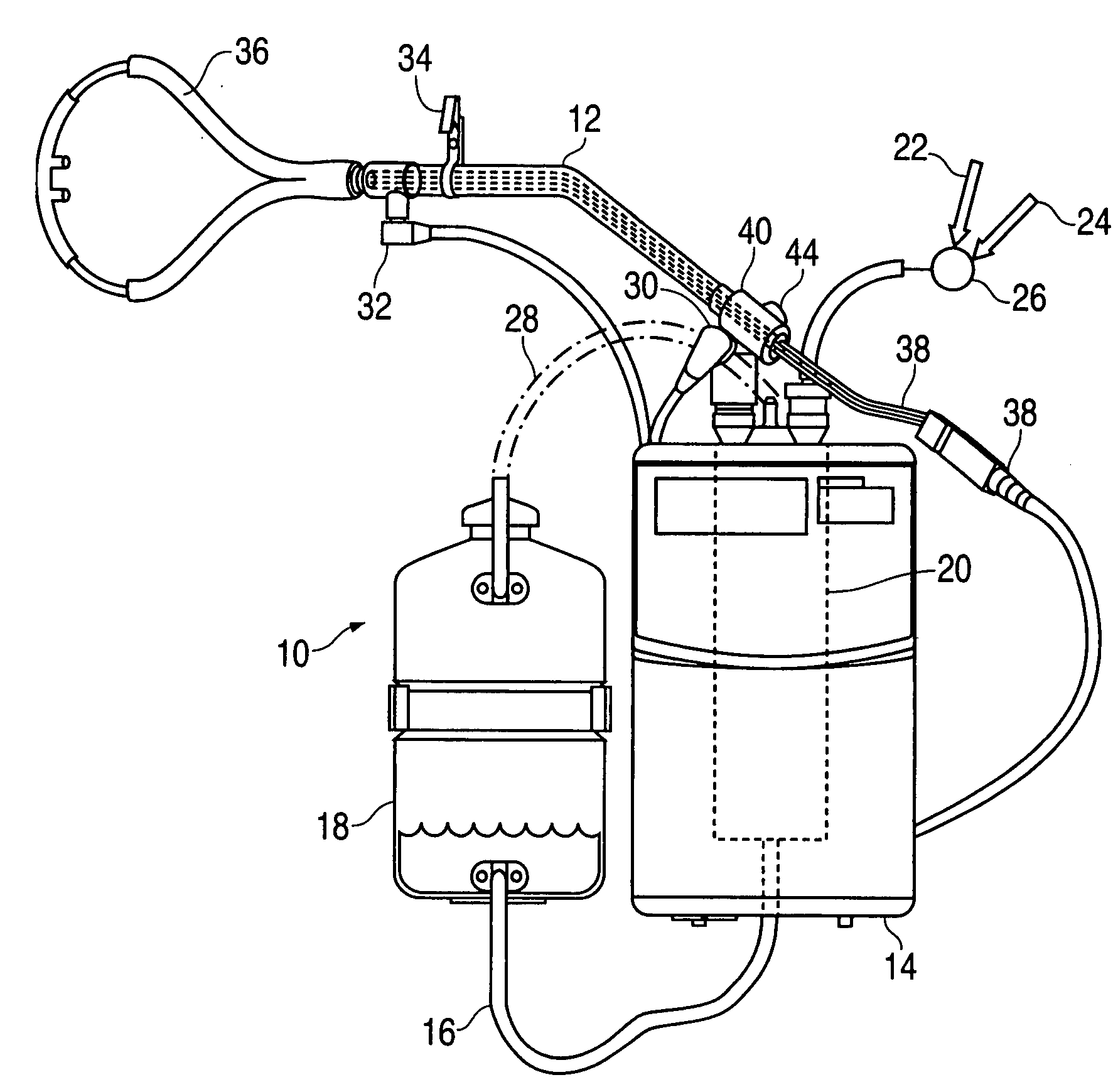
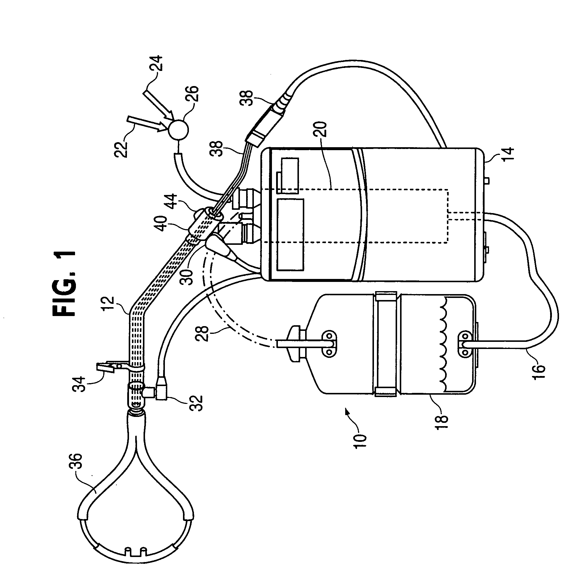
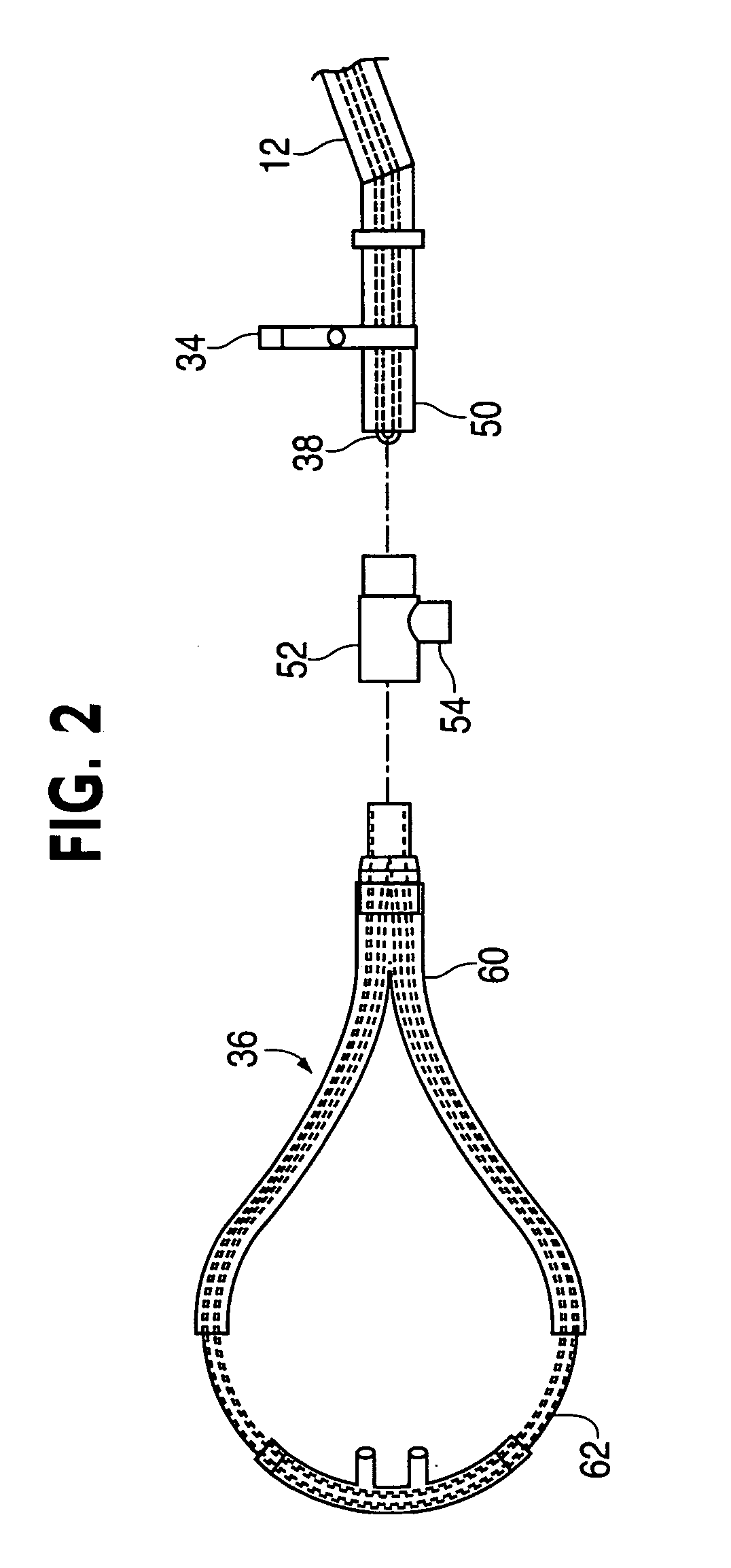
[0006]The foregoing needs are met, to a great extent, by the present invention, wherein in one aspect an apparatus is provided that in some embodiments provides a respiratory breathing circuit that prevents heat loss and condensation in a flow of humidified air supplied through a conduit from a humidification system to a patient interface, such as a nasal cannula. The present invention accomplishes this by providing a number of configurations in the breathing circuit that either: (a) directly impede heat loss or insulate the flow of a humidified gas therein, or (b) provide a heating source inside the circuit along the length of the circuit to indirectly prevent net heat loss from the circuit tubing by providing thermal energy that is lost to convective, conductive, or radiative heat loss by the gas as it flows through the system. In either case, the present invention utilizes a temperature, humidity, or other flow quality measuring probe disposed at the distal end of the circuit near the patient interface to actively measure the corresponding quality of the humidified gas flow so as to provide feedback and information to the system. An additional safety device in the form of a pressure relief valve may be included with the circuit architecture to prevent a pressure build-up and / or structural failure, as well as to alert the surroundings of such an event.

Problems solved by technology

The loss of heat by the flow of fluid along a length of the tubular conduit is actively impeded.

Method used


Image

  • High flow respirator circuit
  • High flow respirator circuit
  • High flow respirator circuit

Examples


Embodiment Construction

[0017]The invention will now be described with reference to the drawing figures, in which like reference numerals refer to like parts throughout. An embodiment in accordance with the present invention provides a respiratory breathing circuit that prevents heat loss and condensation in a flow of humidified air supplied through a conduit from a humidification system to a patient interface, such as a nasal cannula. The circuit is part of an overall gas humidification system that supplies a high flow of respiratory breathing air to a patient through a patient interface. The present invention directly impedes heat loss and / or insulates the flow of a humidified gas through the circuit, and in one embodiment provides a heating source inside the circuit along the length of the circuit to prevent net heat loss from the circuit tubing. A temperature, humidity, or other flow quality measuring probe can be disposed at the distal end of the circuit near the patient interface to actively measure ...


PUM


Abstract

A respiratory breathing circuit prevents heat loss and condensation in a flow of humidified air through a conduit from a humidification system to a patient interface, such as a nasal cannula. The circuit directly impedes heat loss or insulates the flow of a humidified gas therein, and provides a heating source inside the circuit along the length of the circuit to prevent net heat loss from the circuit tubing by providing thermal energy and / or insulation to impede convective, conductive, or radiative heat loss by the gas as it flows through the system. A temperature, humidity, or other flow quality measuring probe is disposed at the distal end of the circuit near the patient interface to actively measure a corresponding quality of the humidified gas flow to provide feedback to the system. A pressure relief valve is provided on the circuit to prevent a pressure build-up and / or structural failure.

Description

FIELD OF THE INVENTION[0001]The present invention relates generally to medical devices. More particularly, the present invention relates to a respiration circuit for providing a continuous high flow of heated and humidified and heated gases to a patient.BACKGROUND OF THE INVENTION[0002]Respiratory therapy systems using mechanical ventilation for moving gas into a patient's lungs commonly incorporate a humidifier along the respiratory circuit in order to heat or humidify the respiratory gas directed to the patient. Examples of such humidifiers are disclosed in U.S. Pat. Nos. 4,110,419, 4,172,105, 4,195,044, 4,500,480 and 4,674,494. Ventilator circuits and other tubing apparatus are designed to direct breathing gas to the patient, with a ventilator or other gas source supplying the gas to be breathed under pressure or at other elevated flow rates at breathing rates and breath gas volumes prescribed to meet the patient's requirements.[0003]Typically, the breathing gas is humidified by ...

Claims


Application Information

Patent Timeline
IPC IPC(8): A61M16/00
CPCA61M16/0666A61M16/209A61M16/0816A61M16/1075A61M16/16A61M16/162A61M16/208A61M2205/3368A61M2205/3633A61M2205/581A61M16/0858A61M16/109A61M16/1095A61M16/142A61M16/08A61M16/0672A61M16/0841
Inventor ROTH, GARYFITZWATER, DENNISBURK, MARC
Owner TELEFLEX MEDICAL INC
Learn More