Timepiece

a timepiece and bezel technology, applied in the field of timepieces, can solve the problems of time and effort, inability to reversely rotate the bezel, and low reliability of retaining the bezel to the desired rotation position, so as to avoid being carelessly rotated and easy to perform the position alignment of the bezel

Active Publication Date: 2008-03-20
SEIKO INSTR INC
View PDF8 Cites 16 Cited by
  • Summary
  • Abstract
  • Description
  • Claims
  • Application Information

AI Technical Summary

Benefits of technology

[0009]It is an aspect of the present invention to provide a timepiece in which a position alignment of the bezel is easy, and the position-aligned bezel can be made so as not to be carelessly rotated.
[0011]In the present invention, by the fact that the lock member is moved to the retracted position, a restriction of the click member is released. Under this released state, it becomes possible to rotation-operate the click member. When the bezel is rotated, since the click member is vertically moved by a quantity approximately corresponding to a height of a convex of the engagement part by the convex of the engagement part of the bezel and a force of the biasing body to thereby carry out a click operation engaging with and disengaging from a concave of the engagement part of the bezel, it is possible to give the click feeling each time by the click member. Together with this, since a rotation direction of the bezel is not limited to one direction, in a case where a rotation of the bezel is performed excessively, it is possible to easily align the bezel to a predetermined position by being reversely rotation-operated without requiring, an effort for rotating by approximately one rotation again.
[0013]Since this locked state can be maintained unless it is artificially released, even if there is the fact that an external force attempting to rotate the bezel acts on it during the timepiece is carried, the position-aligned bezel can be retained so as not to be rotated carelessly.
[0015]In the mode of this invention, since the lock member can be moved by directly contacting a user's finger tip to the operation member to thereby operate this operation member, the lock member can be simply, selectively moved to the retention position or the retracted position without requiring any tool, and it is excellent in handling ability.
[0019]In the mode of this invention, it is possible to stabilize a movement of the click member by sliding the click member in the accommodation hole of the case band and, since the hemispherical part of the click member is engaged with and disengaged from the engagement part of the bezel, an engagement / disengagement operation of the click member in regard to the irregularities of the engagement part when giving the click feeling is smooth.
[0022]According to the present invention, it is possible to provide a timepiece in which, by releasing the lock state of the click member, the position alignment of the bezel can be easily performed and, by making the click member into the lock state, the position-aligned bezel can be retained so as not to be carelessly rotated.

Problems solved by technology

In the conventional example of the above click ball type, although the bezel can be rotated in any direction of the clockwise direction and the counterclockwise direction, since a retention of the bezel to the desired rotation position depends only on a force of the coil spring, a reliability for retaining the bezel to the desired rotation position is low.
Further, in the conventional example of the leaf spring type, since the rotation of the bezel is regulated to only one direction, in a case where the bezel is rotation-operated while slightly deviating from the desired rotation position due to a wrong operation, it is impossible to reversely rotate the bezel.
Therefore, the bezel must be aligned with the desired rotation position by being rotated again by approximately one rotation, so that time and effort are required.
Not only it, in a case where, at a carrying time of the timepiece, an external force acts in a direction along which the rotation of the bezel is allowed, there is also a fear that the bezel is carelessly rotated.

Method used


Image

  • Timepiece
  • Timepiece
  • Timepiece

Examples


Embodiment Construction

[0031]Hereunder, one embodiment of the present invention is explained by referring to FIG. 1-FIG. 8.

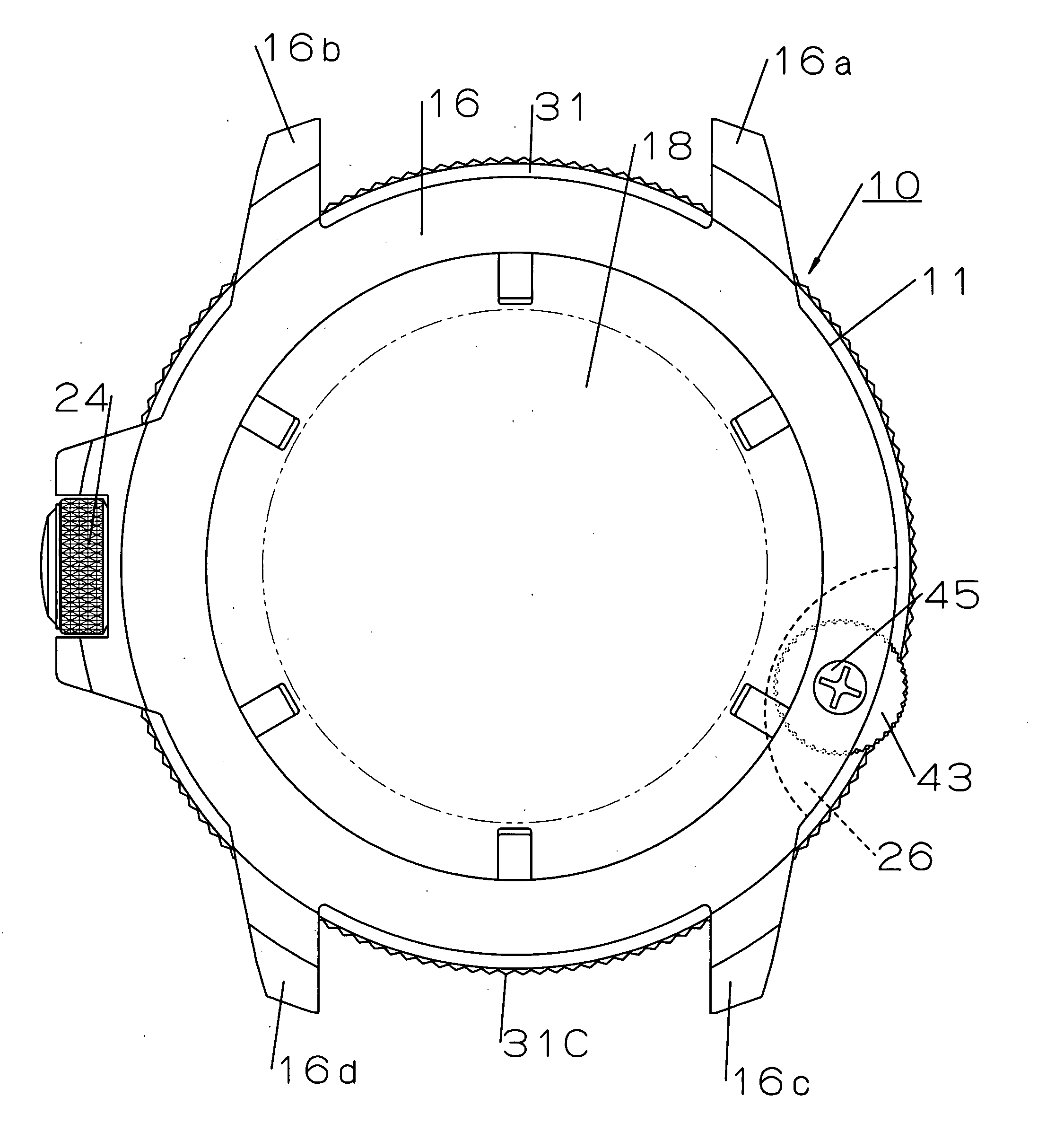
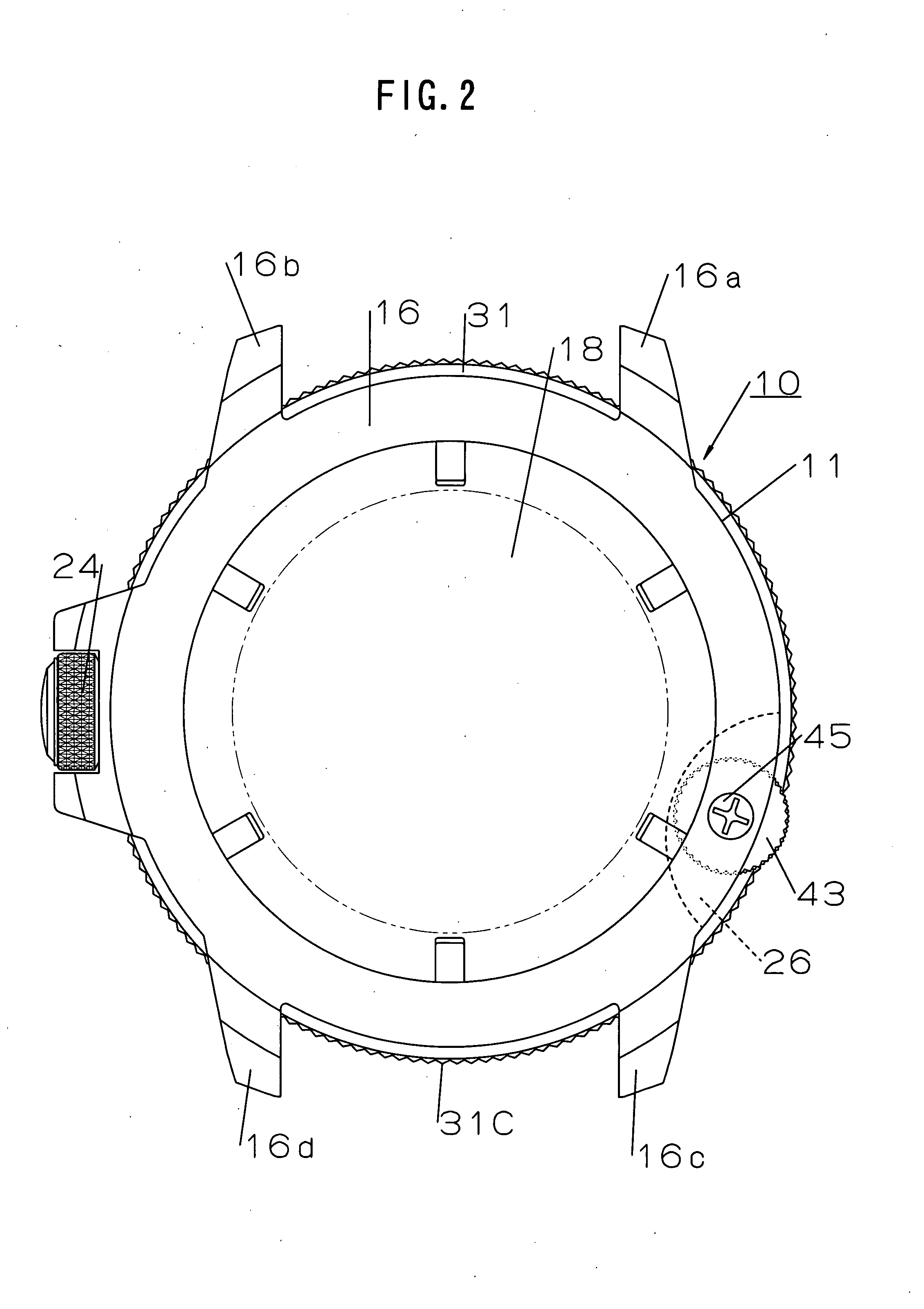
[0032]In FIG. 1, a reference numeral 10 denotes a portable timepiece used while being worn to an arm for instance. In a timepiece armor assembly 11 that this portable timepiece 10 possesses, there are accommodated a timepiece movement 13 (shown in FIG. 3 and FIG. 4) driving indication hands 12, a dial 14 attached to this timepiece movement 13, a frame-like member 15 (shown in FIG. 3 and FIG. 4) retaining the timepiece movement 13 to the timepiece armor assembly 11, and the like.

[0033]As shown in FIG. 1-FIG. 4, the timepiece armor assembly 11 possesses a case band 16 which is desirably made of a metal and annularly made, a cover glass 17 is fluid-tightly mounted to one face (front face) in a thickness direction of the case band 16, and a case back 18 is formed in the other face (back face) in the thickness direction of the case band 16 while being detachably meshed. The indication hand...


PUM


Abstract

To provide a timepiece in which a position alignment of a bezel is easy, and a position-aligned bezel can be made so as not to be carelessly rotated. A portable timepiece possesses a case band, an annular bezel, a click member, a coil spring, and a lock member. In the case band, there are provided an annular bezel disposition groove opening upward and to an outer periphery face, and an accommodation hole extending in a vertical direction while opening to a bottom face of this groove. Bezel is disposed, while being fitted to the disposition groove, so as to be rotatable in both directions of a clockwise direction and a counterclockwise direction in regard to the case band. A click member engaging with and disengaging from an engagement part comprising plural irregularities juxtaposed in a rotation direction in a back face of the bezel facing on the bottom face is accommodated in the accommodation hole so as to be vertically movable. In the accommodation hole, there are accommodated the spring pushing the click member to the engagement part, and the lock member. The lock member moves between a retention position retaining the click member to a state in which this member engages with the engagement part and a retracted position allowing a click operation of the click member, by an operation from an outside of the case band.

Description

BACKGROUND OF THE INVENTION[0001]1. Field of the Invention[0002]The present invention is concerned with a timepiece used while being carried like a wristwatch, a pocket watch or the like, and relates especially to a timepiece possessing a rotatable bezel.[0003]2. Description of the Related Art[0004]Hitherto, the bezel rotatably disposed in a case band is made so as to be retained in a desired operative position by a constitution giving a click feeling following upon its rotation operation. As a constitution for it, there are known a click ball type and a leaf spring type.[0005]The click ball type possesses a constitution in which, in a back face of the bezel, there is provided a click groove formed with engagement teeth comprising plural irregularities juxtaposed in a rotation direction of this bezel and, in the case band, there are provided a steel ball engaged with and disengaged from the engagement teeth, and a coil spring pushing this steel ball to the engagement teeth. In this ...

Claims


Application Information

Patent Timeline
Patent Type & Authority Applications(United States)
IPC IPC(8): G04B37/00
CPCG04B19/283G04B19/286
Inventor HIRANUMA, HARUKIITOH, KINSHUROHOZUMI, YOSHIO
Owner SEIKO INSTR INC
Why Eureka
Try Eureka