Scanning interferometric methods and apparatus for measuring aspheric surfaces and wavefronts

Active Publication Date: 2008-03-20
ZYGO CORPORATION
View PDF17 Cites 28 Cited by
  • Summary
  • Abstract
  • Description
  • Claims
  • Application Information

AI Technical Summary

Benefits of technology

[0032]In one aspect of the invention, a reference wavefront is generated from a known origin along a scanning axis. A test optic is aligned on the scanning axis and selectively moved along it relative to the known origin so that the reference wavefront intersects the test optic at the apex of the aspherical surface and at one or more radial positions where the reference wavefront and the aspheric surface intersect at points of common tangency (“zones”) to generate interferograms containing phase information about the differences in optical path length between the center of the test optic and the one or more radial positions. The interferograms are imaged onto a detector to provide an electronic signal carrying the phase information. The axial distance, ν, by which the test

Problems solved by technology

In addition, lens surfaces in multi-element lithography lenses operating at wavelengths of 193 nm and 157 nm are made aspherical to lower the number of elements made, which are of rare and expensive materials.
So even the fundamental single lens element with either spherical or aspherical surfaces can only be tested properly if one is able to deal with aspherical wavefronts in a test set-up.
The measurement of aspherical surfaces and wavefronts has been very difficult because of the large departure from the best fitting sphere.
But, it is obvious that the same difficulties exist for this type of testing because, again, an aspherical wavefront is produced.
Nevertheless, the final accuracy is questionable because of accumulation of measurement errors and the uncertainty of the homogeneity within the lens material.
While these techniques have utility for many applications, they are limited in their operational capabilities or precision compared with those needed for today's evolving lithography applications.
Contacting and non-contacting stylus based profilers mechanically scan the aspherical surface under test and, therefore, are slow because they measure only a few data points at a time.
Slow techniques are very susceptible to measurement errors due to temperature variations during the measurement.
The same limitations apply to contacting and non-contacting stylus based coordinate measuring machines.
Scanning white light interferometers have many of the same limitations as spherical wavefront interferometers.
Lateral and radial shearing interferometers usually measure the slope of the surface under test and thereby introduce measurement errors during the reconstruction of the surface under test via integration of the slopes.
This latter type of limitation applies to differential types of profiling techniques as well.
Sub-aperture stitching interferometers introduce serious measurement errors in the stitching process.
Interferometers using computer generated holograms are susceptible to errors introduced by the CGH and stray Moire patterns.
It is also difficult to calibrate, i.e., know the calibration of the CGH.
Point diffraction interferometers are a class of spherical wavefront interferometers, and therefore, have many of the same limitations, as well as poor lateral spatial resolution.
None of the prior art approaches is entirely satisfactory since each involves a trade-off that places long lead times on the design of the measurement apparatus and method, requires additional fabrication, increases the difficulty of using and calibrating the measurement apparatus, decreases the accuracy and precision, and greatly increases the cost and delivery time of the aspherical optical element.

Method used


Image

  • Scanning interferometric methods and apparatus for measuring aspheric surfaces and wavefronts
  • Scanning interferometric methods and apparatus for measuring aspheric surfaces and wavefronts
  • Scanning interferometric methods and apparatus for measuring aspheric surfaces and wavefronts

Examples


Embodiment Construction

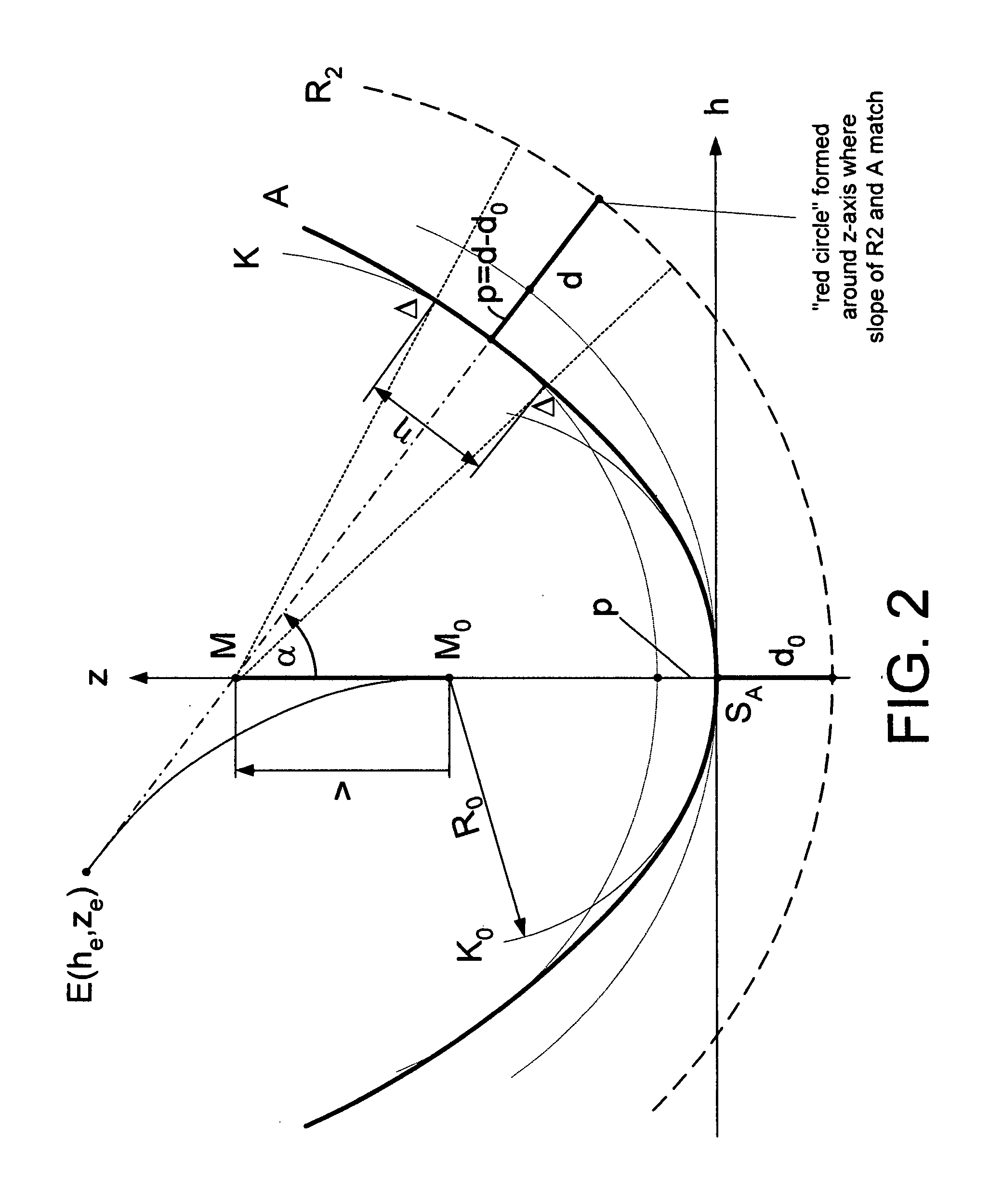
[0069]The present invention relates generally to interferometric apparatus and methods and particularly to interferometric apparatus and associated algorithms by which the shapes of aspheric surfaces and wavefronts can be measured and compared with their designs. To achieve this, the invention utilizes interferometric measurements in object space, where a test surface resides in an interferometric cavity, and their relationships to parameters and detector pixels in image space, where interferograms are imaged on a detector comprising an array of pixels. As a part to be measured is scanned along a scan axis with a known wavefront from the reference surface, the position of the part with respect to reference is interferometrically measured where the local slopes of the reference and part match to generate quantitative information in object space about the axial location of the coordinate of the position where these local slopes match. Along with this information, the vertical location...


PUM


Abstract

Interferometric scanning method(s) and apparatus for measuring test optics having aspherical surfaces including those with large departures from spherical. A reference wavefront is generated from a known origin along a scanning axis. A test optic is aligned on the scanning axis and selectively moved along it relative to the known origin so that the reference wavefront intersects the test optic at the apex of the aspherical surface and at one or more radial positions where the reference wavefront and the aspheric surface intersect at points of common tangency (“zones”) to generate interferograms containing phase information about the differences in optical path length between the center of the test optic and the one or more radial positions. The interferograms are imaged onto a detector to provide an electronic signal carrying the phase information. The axial distance, ν, by which the test optic is moved with respect to the origin is interferometrically measured, and the detector pixel height corresponding to where the reference wavefront and test surface slopes match for each scan position is determined. The angles, α, of the actual normal to the surface of points Q at each “zone” are determined against the scan or z-axis. Using the angles, α, the coordinates z and h of the aspheric surface are determined at common points of tangency and at their vicinity with αmin≦α≦αmax, where αmin and αmax correspond to detector pixels heights where the fringe density in the interferogram is still low. The results can be reported as a departure from the design or in absolute terms.

Description

CROSS-REFERENCE TO RELATED APPLICATION[0001]This application claims the benefit of priority from U.S. Provisional Patent Application No. 60 / 845,731 filed on Sep. 19, 2006 and entitled SCANNING INTERFEROMETRIC METHODS AND APPARATUS FOR MEASURING ASPHERIC SURFACES AND WAVEFRONTS, the entire contents of which are incorporated herein by reference.FIELD OF THE INVENTION[0002]In general, this invention relates to the field of interferometry and, in particular, to the high accuracy measurement of aspherical surfaces and wavefronts in an absolute manner.BACKGROUND OF THE INVENTION[0003]Aspherical surfaces have become more and more important in modem optical systems because they offer a higher number of parameters for simplifying systems while optimizing their performance. This can lead to systems with less surfaces, less weight, smaller dimensions and higher states of correction, to mention only a view advantages. This is especially true in fields where a high number of optical surfaces are...

Claims


Application Information

Patent Timeline
IPC IPC(8): G01B11/02
CPCG01B11/2441G01M11/025G01M11/0271
Inventor KUCHEL, MICHAEL
Owner ZYGO CORPORATION
Why Eureka
Try Eureka