
Secure memory storage device

Inactive Publication Date: 2008-03-13
IBM CORP
View PDF4 Cites 13 Cited by
  • Summary
  • Abstract
  • Description
  • Claims
  • Application Information

AI Technical Summary

Benefits of technology

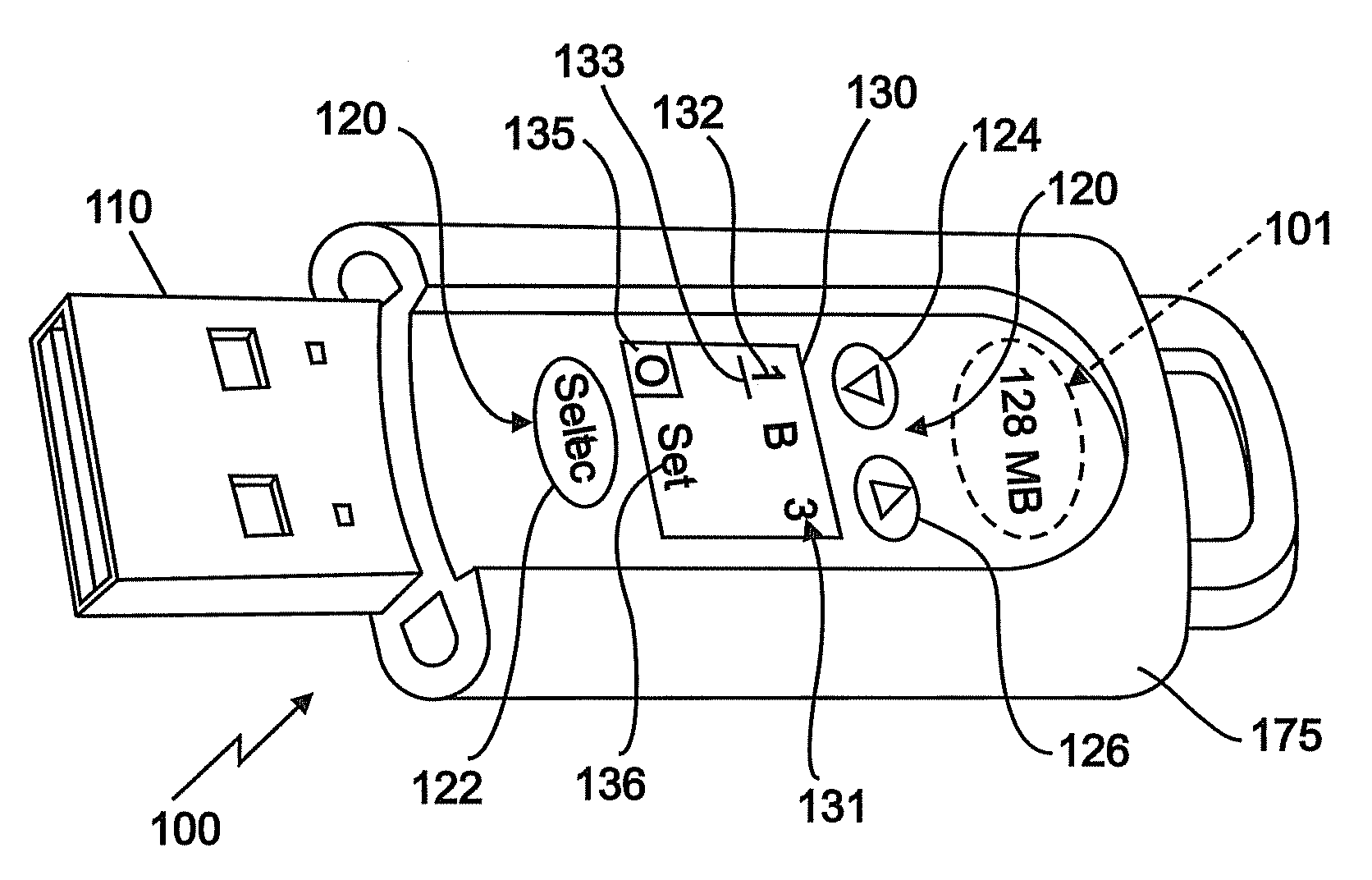
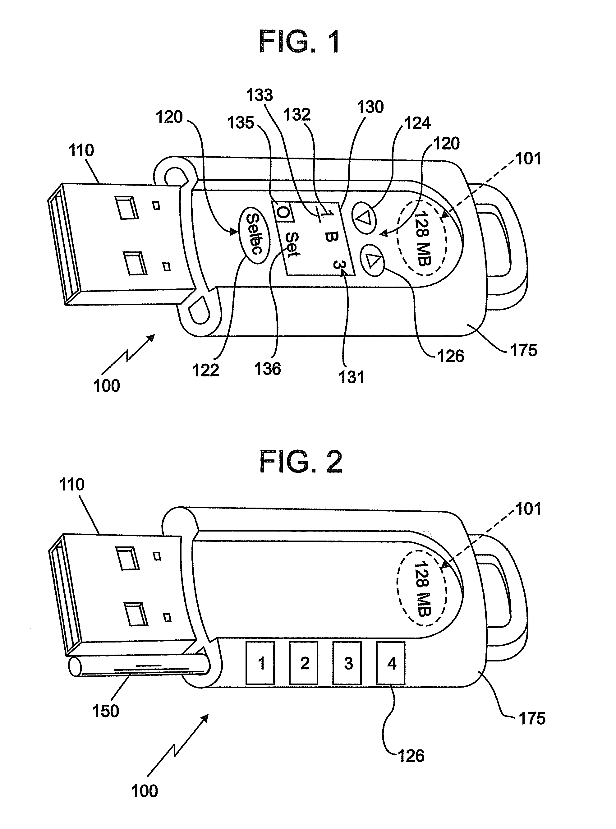
[0008]An embodiment of the invention provides an electronic memory device configured to store and transfer data with a host device via a memory device connector and a mating host connector. The electronic memory device includes a memory storage configured for signal communication with the memory device connector, a plurality of key buttons, and a display disposed upon the memory device, the display configured to display the security code. The key buttons are disposed upon the memory device and are configured to provide selection and entry of each field of a security code comprising a plurality of fields. The memory device is configured to allow data transfer to or from the memory storage in response to entry of the security code, but to prevent data transfer to or from the memory storage prior to entry of the security code and in response to disconnection of the memory device from the host device.
[0009]A further embodiment of the invention provides an electronic memory device configured to store and transfer data with a host device via a memory device connector and a mating host connector. The electronic memory device includes a memory storage configured for signal communication with the memo

Problems solved by technology

Many of these types of memory devices lack any capability to secure the data stored on the device.
However, the confidential data stored in the memory devices made according to this design may be stolen by hacker programs or otherwise vulnerable to brute-force methods of attack.
Further, many designs of present industrial computers do not have a keyboard, and thus the “password-type design” cannot be used for the transfer of data with these industrial computers.
Incorporation of single-purpose number keys to enter a numeric password may provide protection, but such protection is limited to combinations defined, and limited by, the numeric keys.
Although each of these methods may have certain utility, they may compromise device compatibility, physical size limitations, performance, cost factors, and ease-of-use.

Method used


Image

  • Secure memory storage device
  • Secure memory storage device

Examples


Embodiment Construction

[0015]In an embodiment, a secure memory device will be disabled, or unable to allow data transfer, until the appropriate combination is entered into the integrated device lock. In an embodiment, the lock is implemented using electronic components, including digital displays and pushbuttons. In another embodiment, the lock is a mechanical lock utilizing small dials, sliders, or other mechanical controls to engage a physical means to prevent the attachment of the memory device to any host device. An embodiment of the invention will provide a greater number of elements in the security code. In an embodiment the circuitry is powered by a small long-life battery such as a lithium battery, for example. In another embodiment, the circuitry is powered by a small rechargeable battery. In an embodiment, the memory device is configured to recharge the rechargeable battery upon connection of the memory device to a host device. In an embodiment, the device can combine the mechanical lock to prev...


PUM


Abstract

An electronic memory device configured to store and transfer data with a host device via a memory device connector and a mating host connector is disclosed. The electronic memory device includes a memory storage, a plurality of key buttons disposed upon the memory device, and a display disposed upon the memory device. The plurality of key buttons is configured to allow entry of a security code comprising a plurality of fields, and the display configured to display the security code. The memory device is configured to allow data transfer to or from the memory storage in response to entry of the security code, but to prevent data transfer to or from the memory storage prior to entry of the security code and in response to disconnection of the memory device from the host device.

Description

TRADEMARKS[0001]IBM® is a registered trademark of International Business Machines Corporation, Armonk, N.Y., U.S.A. Other names used herein may be registered trademarks, trademarks or product names of International Business Machines Corporation or other companies.BACKGROUND OF THE INVENTION[0002]1. Field of the Invention[0003]This invention relates to memory storage devices, and particularly to memory storage device data security.[0004]2. Description of the Background[0005]The use of small, portable memory devices such as USB keys, flash drives, compact flash memory, memoryStiks, and other such devices has flourished. The small size of these devices allows them to be integrated with many common everyday items, such as key chains, and pens, for example. They may be used with cameras, personal digital assistants (PDAs), phones, digital media players, as well as portable memory devices.[0006]Many of these types of memory devices lack any capability to secure the data stored on the devi...

Claims


Application Information

Patent Timeline
IPC IPC(8): G06F12/14
CPCG06F12/1433G06F2221/2153G06F21/78
Inventor MILLER, STEVEN M.
Owner IBM CORP
Learn More