
Liquid crystal panel and liquid crystal display

a liquid crystal display and liquid crystal panel technology, applied in non-linear optics, instruments, optics, etc., can solve the problems of increasing the cost of the conventional mva-lcd, restricting the viewing angle of the lcd, etc., and achieve the effect of wide viewing angle and low cos

Inactive Publication Date: 2008-03-13
WINTEK CORP
View PDF4 Cites 108 Cited by
  • Summary
  • Abstract
  • Description
  • Claims
  • Application Information

AI Technical Summary

Benefits of technology

[0007]Accordingly, the present invention provides a liquid crystal panel featuring a wide viewing angle and a low cost.
[0008]The present invention provides a liquid crystal display (LCD) featuring a wide viewing angle and a low cost.
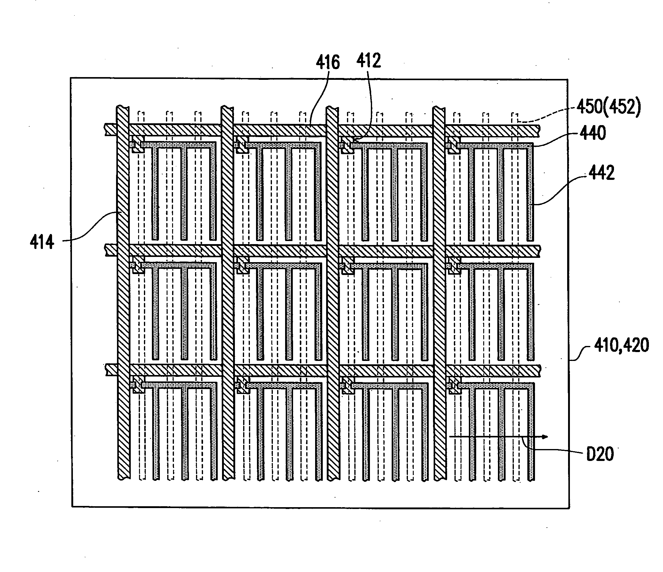
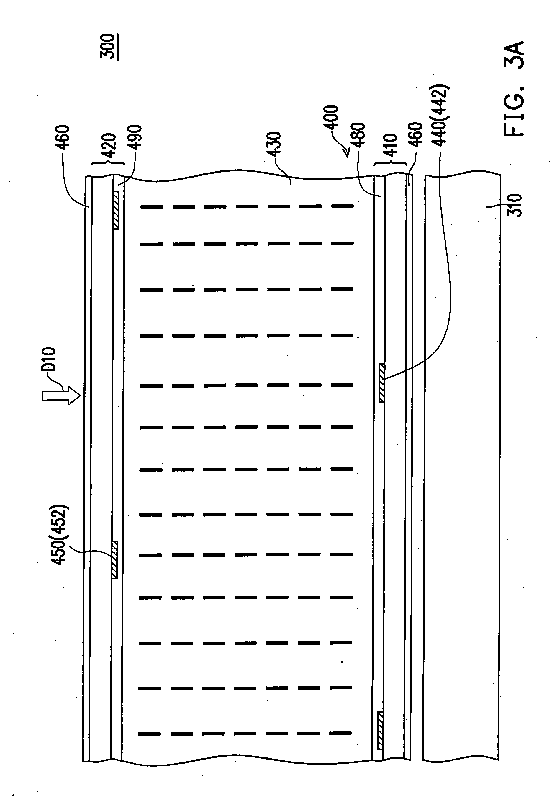
[0025]In summary, according to the liquid crystal panel and the LCD of the present invention, a display region with at least two domains is developed through an adoption of the positive liquid crystal layer and a horizontal electric field formed by the staggered first and second strip-shape portions, achieving a wide viewing angle. Furthermore, since the positive liquid crystals are less expensive than the negative liquid crystals, metal can be directly used during the process of manufacturing the pixel electrodes so as to avoid a transparent electrode (ITO or IZO) process and to yield micro reflectance. Thereby, the costs of the liquid crystal panel and the LCD disclosed in the present invention can be reduced.

Problems solved by technology

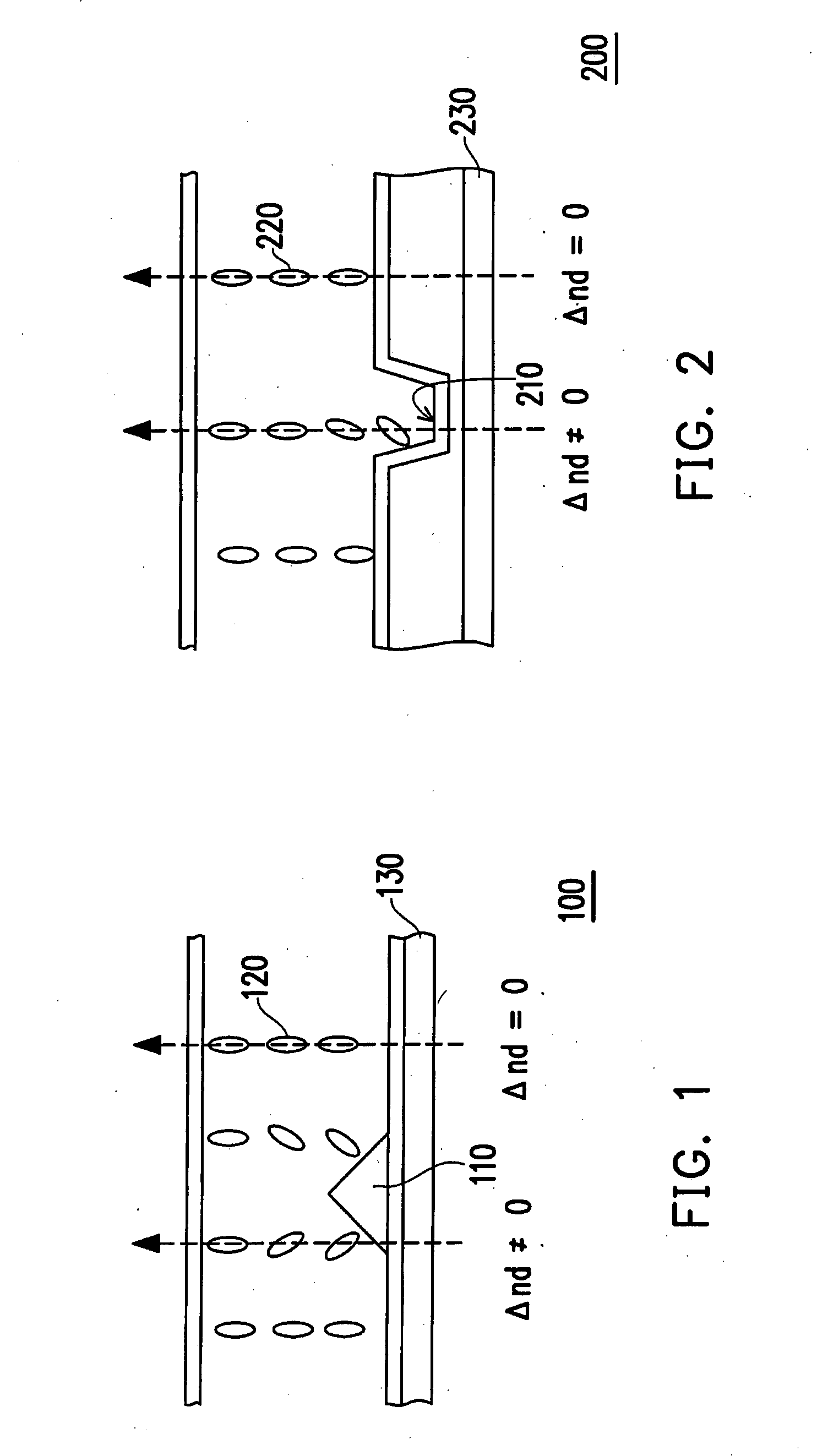
However, the viewing angle restriction of the LCD still exists.
Furthermore, it is customary for the liquid crystal molecules 120 and 220 to be made of negative liquid crystals which are at higher expenses, further increasing the costs of the conventional MVA- LCDs.

Method used


Image

  • Liquid crystal panel and liquid crystal display
  • Liquid crystal panel and liquid crystal display
  • Liquid crystal panel and liquid crystal display

Examples


Embodiment Construction

[0031]FIGS. 3A and 3B are partial sectional views respectively illustrating a liquid crystal display (LCD) before and after a voltage is applied to a liquid crystal layer according to one embodiment of the present invention. FIG. 4 is a top view of the LCD as is shown in FIG. 3A.

[0032]Referring to FIG. 3A, a liquid crystal display (LCD) 300 of the present embodiment comprises a backlight module 310 and a liquid crystal panel 400. The liquid crystal panel 400 is disposed above the backlight module 310 so as to display images through a planar light source provided by the backlight module 310. Given the liquid crystal panel 400 adopts a reflective or a transflective design, it is of certainty that the liquid crystal panel 400 is still capable of displaying images without jointly utilizing the backlight module 310. The backlight module 310 is any of an apparatus which provides a planar light source; therefore, a detailed description of the backlight module 310 is then omitted.

[0033]Refe...


PUM


Abstract

A liquid crystal display (LCD) and a liquid crystal panel thereof are provided. The LCD includes a backlight module and the liquid crystal panel disposed thereon. The liquid crystal panel has a first substrate, a second substrate, and a positive liquid crystal layer. The first substrate has a plurality of pixel electrodes, and each pixel electrode has a plurality of first strip-shape portions. The second substrate has a common electrode, and the common electrode has a plurality of second strip-shape portions. The positive liquid crystal layer is interposed between the pixel electrodes of the first substrate and the common electrode of the second substrate and is vertically aligned. The corresponding areas of the first and the second strip-shape portions are staggered.

Description

CROSS-REFERENCE TO RELATED APPLICATION[0001]This application claims the priority benefit of Taiwan application serial no. 95133607, filed on Sep. 12, 2006. All disclosure of the Taiwan application is incorporated herein by reference.BACKGROUND OF THE INVENTION[0002]1. Field of the Invention[0003]The present invention relates to a liquid crystal panel and a liquid crystal display (LCD), and more particularly to a liquid crystal panel and a liquid crystal display (LCD) with wide viewing angles.[0004]2. Description of Related Art[0005]With big leaps in the techniques of manufacturing opto-electronics and semiconductor devices, flat panel displays (FPDs) have been vigorously developed. Among the flat panel displays, the liquid crystal display (LCD) is widely applied to replace the traditional CRT display little by little, and has become the mainstream display product due to its advantages of low operating voltage, free of harmful radiation, light weight, and small and compact size. Howe...

Claims


Application Information

Patent Timeline
IPC IPC(8): G02F1/1335G02F1/1337G02F1/1343
CPCG02F1/134309G02F2001/134318G02F2201/122G02F2001/13706G02F2001/134381G02F1/134381G02F1/134318G02F1/13706
Inventor LEE, CHIAN-CHANGLIU, CHIN-CHANGKUO, CHIEN-CHUNG
Owner WINTEK CORP
Learn More