
Apparatus of triple-electrode dielectric barrier discharge at atmospheric pressure

Inactive Publication Date: 2008-03-13
INST NUCLEAR ENERGY RES ROCAEC
View PDF5 Cites 22 Cited by
  • Summary
  • Abstract
  • Description
  • Claims
  • Application Information

AI Technical Summary

Benefits of technology

[0004]The main purpose of the present invention is to generate stable glow discharge plasmas, to speed up material processing and to process thick materials by increasing the atmospheric pressure plasma density with two properly correlated high voltage power supplies so that the device could be operated in glow discharge mode at a wide discharge gap.
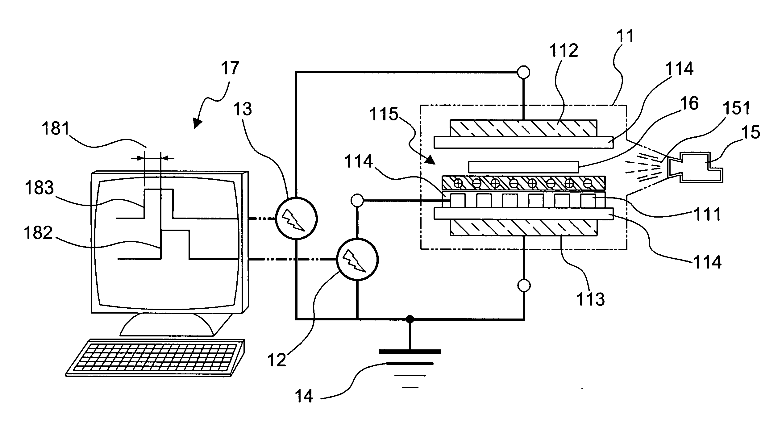
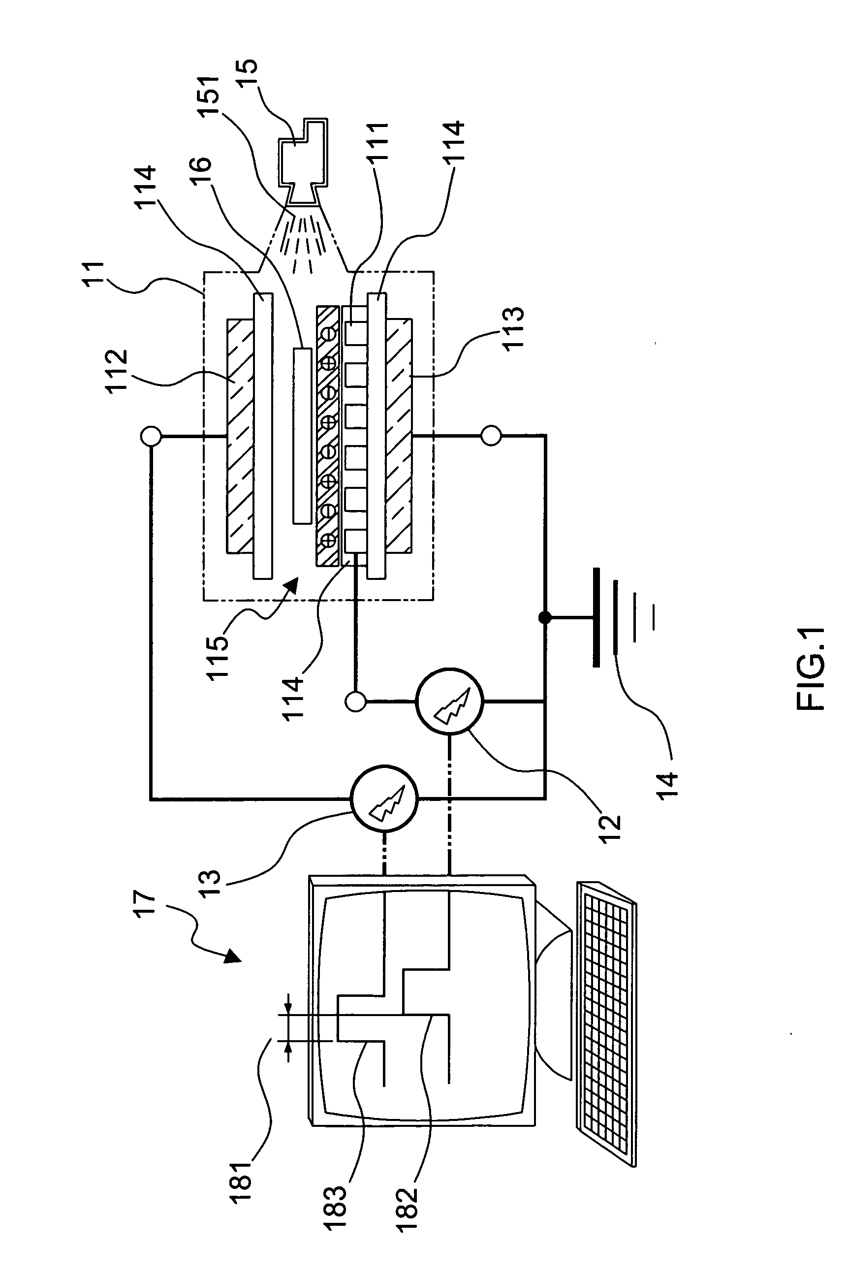
[0005]To achieve the above purpose, the present invention is an apparatus of triple-electrode dielectric barrier discharge (TDBD) at an atmospheric pressure, comprising a plasma chamber, a first power supply, a second power supply, a mass flow controller, a first electrode, a second electrode, a common ground electrode with respect to the first and the second electrode and a dielectric layer and a discharge gap; the first electrode together with the common ground electrode is connected to the first power supply; the second electrode together with the common ground electrode is connected to the second power supply; Therein, the mass flow controller provides and controls various gas in the plasma chamber flowing through the discharge gap to generate discharge plasmas on the surface of the first electrode; the charged particles on the surface of the 1st electrode are attracted by the 2nd electrode so that its discharge could be ignited at lower applied voltage and wider discharge gap than the conventional DBD. Thus, the discharge on the 2nd electrode becomes much easier due to the help of the pre-ionization plasmas generated on the surface of the 1st electrode; and, therefore, the discharge gap can be widened in order to process thick material and to speed up material processing. Accordingly, a novel apparatus of triple-electrode dielectric barrier discharge at an atmospheric pressure is obtained, which could be used to treat thick materials and to speed up its processing.

Problems solved by technology

Besides, there are many other issues in surface processing by DBD, such as narrow discharge gap and low plasma density.
Hence, the prior art does not meet most of users' requirements in practical applications.

Method used


Image

  • Apparatus of triple-electrode dielectric barrier discharge at atmospheric pressure
  • Apparatus of triple-electrode dielectric barrier discharge at atmospheric pressure
  • Apparatus of triple-electrode dielectric barrier discharge at atmospheric pressure

Examples


Embodiment Construction

[0010]The following description of the preferred embodiment is provided to understand the features and the structures of the present invention.

[0011]Please refer to FIG. 1, which is a schematic for the preferred embodiment according to the present invention. As shown in the figure, the present invention is an apparatus of triple-electrode dielectric barrier discharge at an atmospheric pressure, comprising a plasma chamber 11, a first power supply 12, a second power supply 13, 14, a mass flow controller 15, a first electrode 111, a common ground electrode, a second electrode 112, a plurality of dielectric layers 114 and a discharge gap 115, where the first electrode 111 is together with the common ground electrode 113 is connected to the first power supply 12; the second electrode 112 together with the common ground electrode 113 is connected to the second power supply 113; The discharge gap 115 is located above the surface of the dielectric layer 114 on the first electrode 111.

[0012...


PUM

PropertyMeasurementUnit
Timeaaaaaaaaaa
Pressureaaaaaaaaaa
Densityaaaaaaaaaa

Abstract

A dielectric barrier discharge uses three electrodes at an atmospheric pressure. A wide discharge gap can be used and an enhanced plasma density can be achieved so that thick materials can be processed and its processing speed can also be greatly improved.

Description

FIELD OF THE INVENTION[0001]The present invention relates to an apparatus of a dielectric barrier discharge for generating glow discharge plasmas at atmospheric pressure; more particularly, relates to obtaining more stable glow discharge plasmas, wider discharge gap and a higher plasma density to speed up material processing and to process thick materials.DESCRIPTION OF THE RELATED ART[0002]The word “plasma” is used to describe partially ionized gases containing many interacting free electrons, ionized atoms or molecules and free radicals. Non-thermal equilibrium plasma has many applications such as surface modification of polymers, cleaning, etching and thin film deposition. It is known that plasma sources operated at atmospheric pressure have many advantages such as free of vacuum chamber, the potential to achieve higher processing speed and lower processing cost, etc.[0003]The conventional dielectric barrier discharge (DBD) reactor consists of two electrodes with at least one die...

Claims


Application Information

Patent Timeline
IPC IPC(8): C23C16/00
CPCH01J37/32009H01J37/32825H01J37/32587H01J37/32348
Inventor HSIEH, CHENG-CHANGWU, MIEN-WINAI, CHI-FONG
Owner INST NUCLEAR ENERGY RES ROCAEC
Learn More