
Optical film

a technology of optical film and film body, applied in the field of optical film, can solve the problems of affecting the service life and quality of other elements, affecting the appearance of moiré or newton ring, and the inability to meet the demands of many information products that use batteries to provide power when not connected to power lines, so as to reduce optical interference and enhance the brightness of a flat display

Active Publication Date: 2008-03-06
ETERNAL MATERIALS CO LTD
View PDF17 Cites 20 Cited by
  • Summary
  • Abstract
  • Description
  • Claims
  • Application Information

AI Technical Summary

Benefits of technology

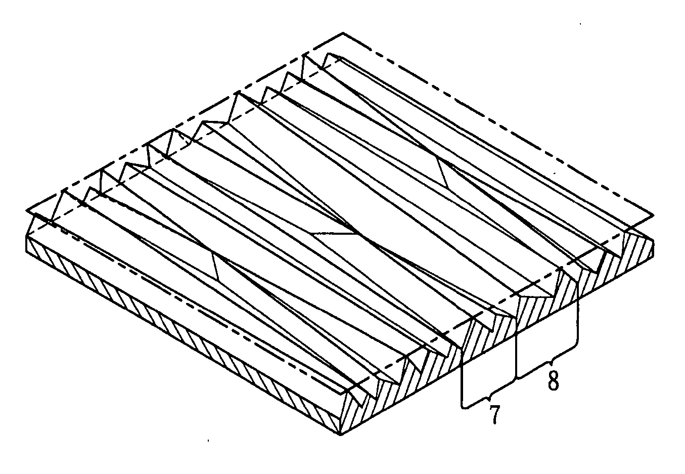
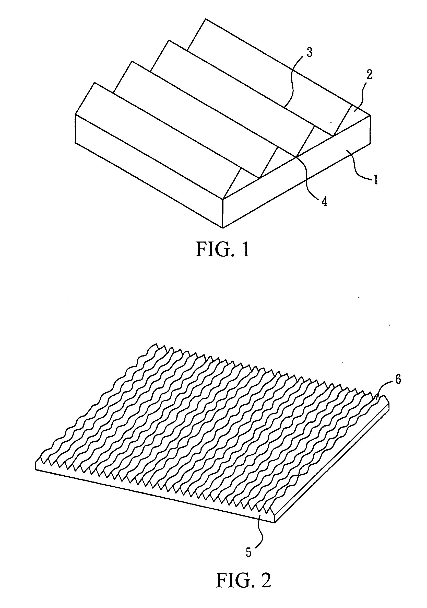
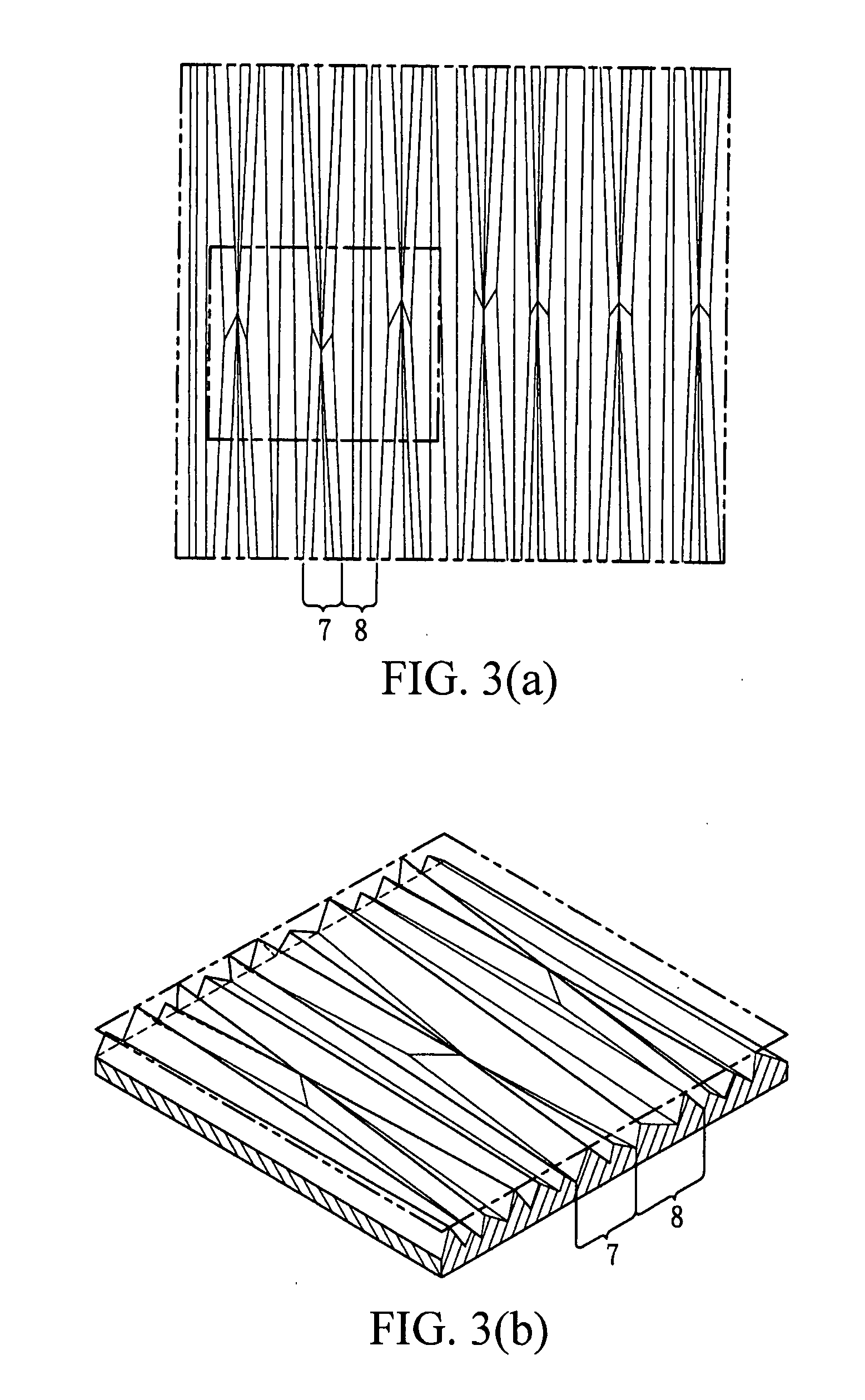
[0008] The present invention is mainly directed to an optical film for enhancing the brightness of a flat display and reducing optical interference. The present invention provides an optical film which includes a transparent substrate and a structured surface layer, wherein the structured surface layer is disposed on the upper surface of the transparent substrate and includes a plurality of non-parallel, adjacent columnar structures.

Problems solved by technology

However, the increase of the number of lamps will easily result in an excessive heat accumulation in LCDs, and thus affect the service life and quality of other elements.
Meanwhile, due to large power consumption, the demands associated with many information products that use batteries to provide power when not being connected to power line cannot be fulfilled.
The brightness enhancing films disclosed in the prior art have regular strip-shaped structures having a fixed width, such that an optical interference caused by the light rays refracted or reflected by other films of the displays or by other light rays refracted or reflected by the brightness enhancing film occurs, thereby resulting in Moiré or Newton ring in appearance.
Therefore, the optical interference cannot be alleviated effectively.
A solution proposed in the industry is to dispose a piece of diffusion film above the brightness enhancing film, which however suffers from the disadvantages associated with increased costs and complex backlight modules.
Moreover, since the conventional brightness enhancing film has a regular brightness enhancing structure, when the brightness enhancing structure is damaged, for example, the apex angle of the prism structure is dented, the light gathering effect will be adversely affected or dark spots occur on the panel.
Therefore, it is necessary for the brightness enhancing films to have a high hardness and undamaged brightness enhancing structure, which however, results in an increase on the preparation cost.

Method used


Image

  • Optical film
  • Optical film
  • Optical film

Examples


example 1

Preparation of the Optical Film of the Present Invention

[0038] 60 g EM210® (2-phenoxyethylacrylate, sold by Eternal Company) and 60 g 624-100® (epoxy acrylate, sold by Eternal Company) were mixed, and then 5 g Chivacureg BP was added as photo initiator (benzophenone, provided by Double Bond Chemical), and the mixture was stirred at 1000 rpm at 50° C. to form a colloidal coating composition.

[0039] The colloidal coating composition was coated onto a PET substrate (U34®, produced by TORAY Company) to form a coating layer, and then a structured surface layer is formed on the coating layer by roller embossing. The structured surface layer includes a plurality of non-parallel, adjacent linear prism patterns. Thereafter, the coating layer was cured by irradiation with energetic radiation at normal temperature.

example 1-1

Property Test on the Optical Film of the Present Invention

[0040] The optical film prepared in Example 1 was tested by SEM, and the results were as shown in FIG. 11. Moreover, the brightness enhancement test of the optical film prepared in Example 1 was carried out with the BM-7® instrument provided by TOPCON Company, and the result was as shown in Table 1.

example 1-2

Property Test on Conventional Brightness Enhancing Film

[0041] A conventional brightness enhancing film was tested by SEM, and the results were as shown in FIG. 12. Moreover, the brightness enhancement test of such film was carried out with the BM-7® instrument provided by TOPCON Company, and the result was as shown in Table 1.

TABLE 1Example No.Brightness GainExample 1-156%Example 1-258%

[0042] As can be seen from Table 1, as compared with the conventional brightness enhancing film, the optical film according of the present invention has a brightness gain of about 99% of that of the conventional brightness enhancing film.


PUM


Abstract

The subject invention provides an optical film comprising a transparent substrate and a structured surface layer, wherein the structured layer is positioned on the upper surface of the substrate and comprises a plurality of non-parallel, adjacent columnar structures. The optical film according to the subject invention can effectively enhance the brightness of a liquid crystal display and reduce the optical interference.

Description

BACKGROUND OF THE INVENTION [0001] 1. Field of the Invention [0002] The present invention relates to an optical film applicable to a flat display. [0003] 2. Description of the Prior Art [0004] Since liquid crystal display (LCD) panels cannot emit light, backlight modules serving as brightness sources become an important element for liquid crystal displays (LCDs), and are also quite important for enhancing display brightness. In the industry, there are many attempts to enhance the brightness of LCD panels, for example, by increasing the number of lamps. However, the increase of the number of lamps will easily result in an excessive heat accumulation in LCDs, and thus affect the service life and quality of other elements. Meanwhile, due to large power consumption, the demands associated with many information products that use batteries to provide power when not being connected to power line cannot be fulfilled. Currently, various optical films are used in backlight modules to enhance ...

Claims


Application Information

Patent Timeline
Patent Type & Authority Applications(United States)
IPC IPC(8): F21V8/00
CPCG02B6/0053G02B5/045G02B5/02G02B5/04
Inventor CHUANG, SHIH-YIWU, GUO-LONG
Owner ETERNAL MATERIALS CO LTD
Learn More