
Projector apparatus

a projector and lens technology, applied in the field of projector apparatus, can solve the problems of difficult assembly and disassembly of lamps and/or lenses, and achieve the effect of improving the fixation structure of lamps

Active Publication Date: 2008-03-06
SANYO ELECTRIC CO LTD +1
View PDF3 Cites 9 Cited by
  • Summary
  • Abstract
  • Description
  • Claims
  • Application Information

AI Technical Summary

Benefits of technology

[0001] This invention relates to a projector apparatus for constructing imaging light to be projected onto a front screen by leading a beam of light from a light source to an optical system, and more particularly to a projector apparatus equipped with an improved lamp fixation structure.

Problems solved by technology

Since this type of fixation structure disadvantageously involves many parts and many assembling processes, assembling and disassembling of the lamp and / or lens is not easy.

Method used


Image

  • Projector apparatus
  • Projector apparatus
  • Projector apparatus

Examples


Embodiment Construction

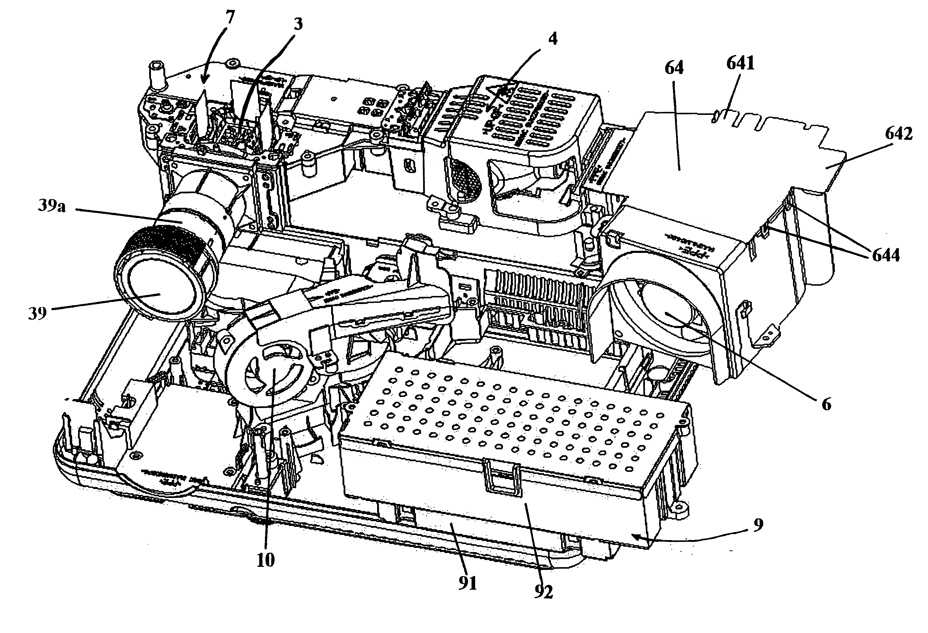
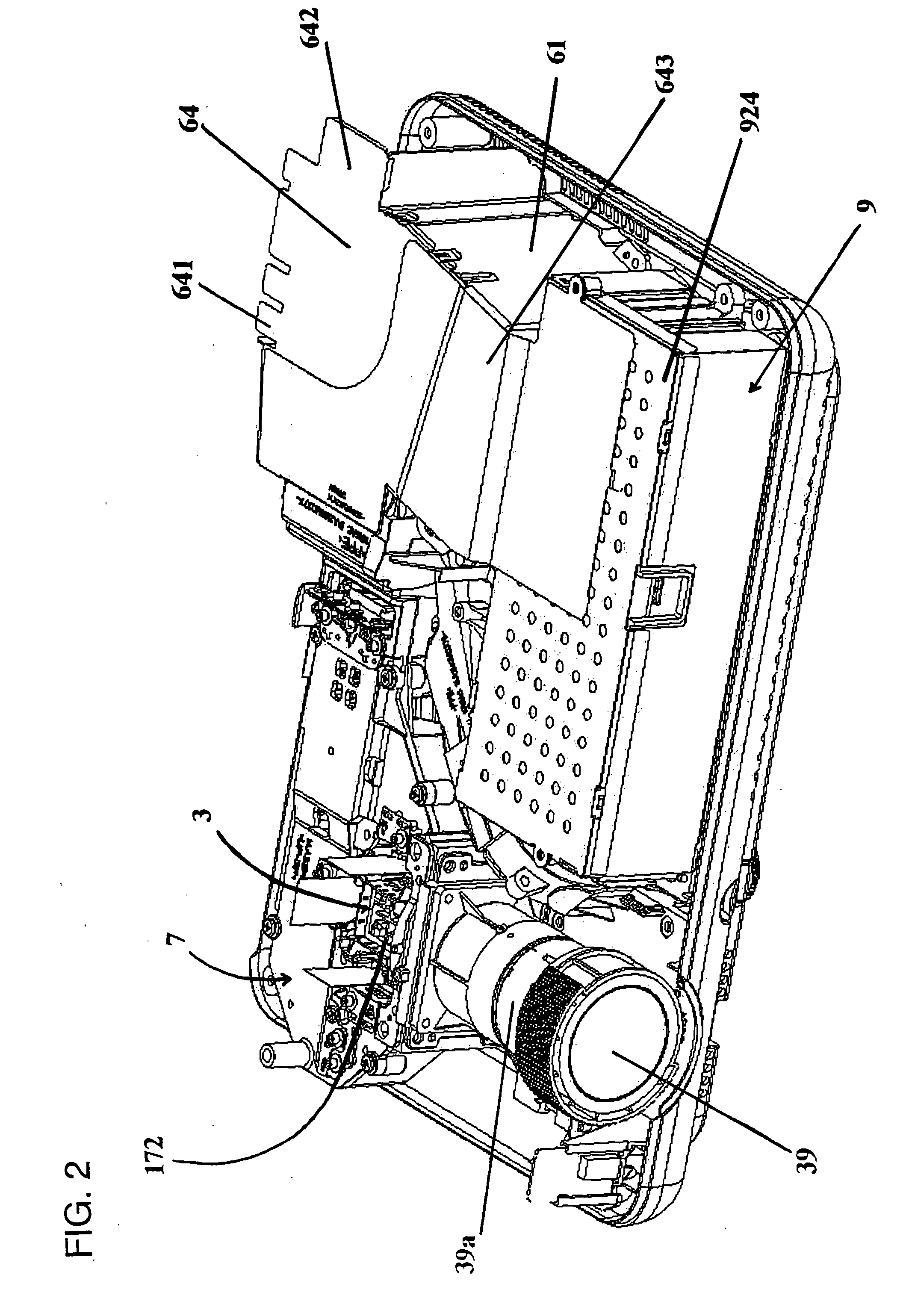
[0046] The invention will now be described in detail by way of example, particularly an LC projector apparatus and related parts, with reference to the accompanying drawings. In what follows, the “front” side of the projector apparatus refers to the side thereof having its projection lens (FIG. 1), and the “right” and “left” of the LC projector apparatus refer to the directions to the “right” and “left” relative to the front side, respectively. It should be understood that terms indicating relative positions of elements such as “bottom”, “side”, “oblique”, and “directly below” are illustrative, and that the relative positions can be conveniently altered as needed.

Overall Arrangement

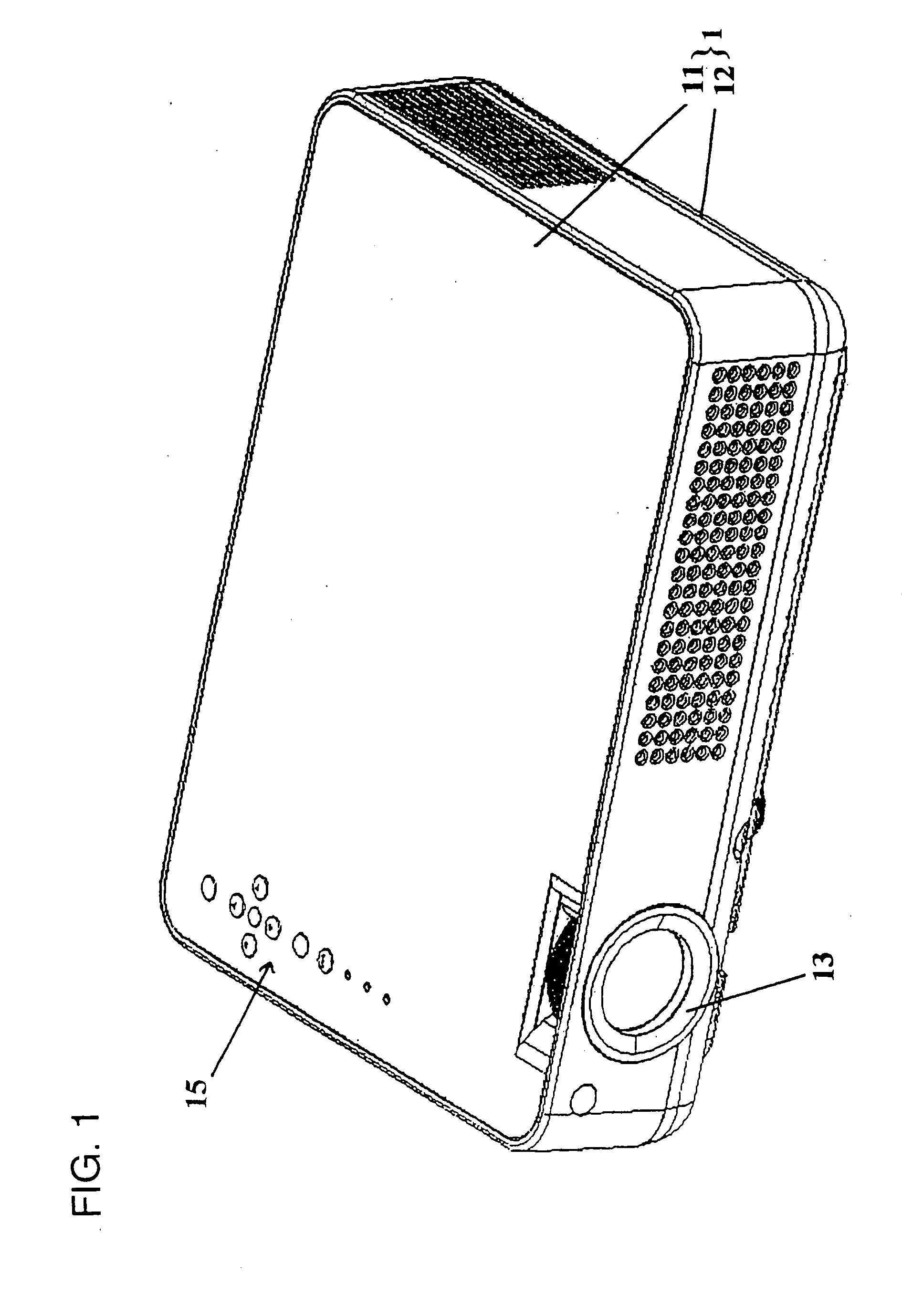
[0047] The LC projector apparatus is provided with a generally flat casing 1 which consists of an upper half section 11 and a lower half section 12, as shown in FIG. 1. Provided on the upper end of the casing 1 is a controller 15 having a multiplicity of buttons for manual operation of the projector ap...


PUM


Abstract

A projector apparatus and a lamp fixation structure for use with the projector apparatus are disclosed. The lamp fixation structure has a lower holder, which includes an integrally formed lower holder lens section and a lower holder lamp section. The lower holder lens section defines a lens fitting slot for fixing a lens, and a lower holder lamp section defines a lamp fitting slot for fixing a lamp. The lens fixing slot includes an upper holder connected to the lower holder. The lamp fixation structure also includes an integrally formed metal holder, which has an elastic top plate, elastic lateral plates, a front plate, an elastic bottom plate, and elastic jointing plates. The inventive lamp fixation structure of the projector apparatus consists of a fewer components and can be assembled in a simple manner, yet it is highly wrought.

Description

FIELD OF THE INVENTION [0001] This invention relates to a projector apparatus for constructing imaging light to be projected onto a front screen by leading a beam of light from a light source to an optical system, and more particularly to a projector apparatus equipped with an improved lamp fixation structure. BACKGROUND OF THE INVENTION [0002] The lamp of a projector apparatus serving as a light source belongs to consumable parts, so that the lamp and the lens of the optical system arranged close to the lamp are integrally designed to be independent from other parts for ease of replacement. In a typical conventional projector apparatus, the lamp is fixed with one or more plastic frames in multiple metal holders. It is often the case in conventional art that the lamp and the lens arranged closest to the lamp are mostly fixed separately. Since this type of fixation structure disadvantageously involves many parts and many assembling processes, assembling and disassembling of the lamp ...

Claims


Application Information

Patent Timeline
IPC IPC(8): G03B21/20
CPCG03B21/145G03B21/20
Inventor KONG, XIANGFEIZHANG, XIANGLINOKAZAKI, SHOJIHUANG, YANSHANRENBUTSU, TADASHISARUWATARI, TOSHIHIROTANG, WENTIANLV, QIANG
Owner SANYO ELECTRIC CO LTD
Learn More