
Switching mode power supply and method of operation

Active Publication Date: 2008-02-28
SEMICON COMPONENTS IND LLC
View PDF12 Cites 21 Cited by
  • Summary
  • Abstract
  • Description
  • Claims
  • Application Information

AI Technical Summary

Benefits of technology

[0008]Various embodiments of the present invention provide a switching mode power supply and a driving method thereof which reduce EMI by changing a switching frequency of a switching device (e.g., transistor), regardless of an input AC voltage.

Problems solved by technology

Electromagnetic interference (EMI) can arise in a SMPS, in part, due to turning on and off a switching device at constant frequency.
A device with high EMI generates noise in other devices using the same power source.
The decrease in the DC-link voltage ripple may reduce the modulation range of the switching frequency, thus resulting in an increase in EMI.

Method used


Image

  • Switching mode power supply and method of operation
  • Switching mode power supply and method of operation
  • Switching mode power supply and method of operation

Examples


Embodiment Construction

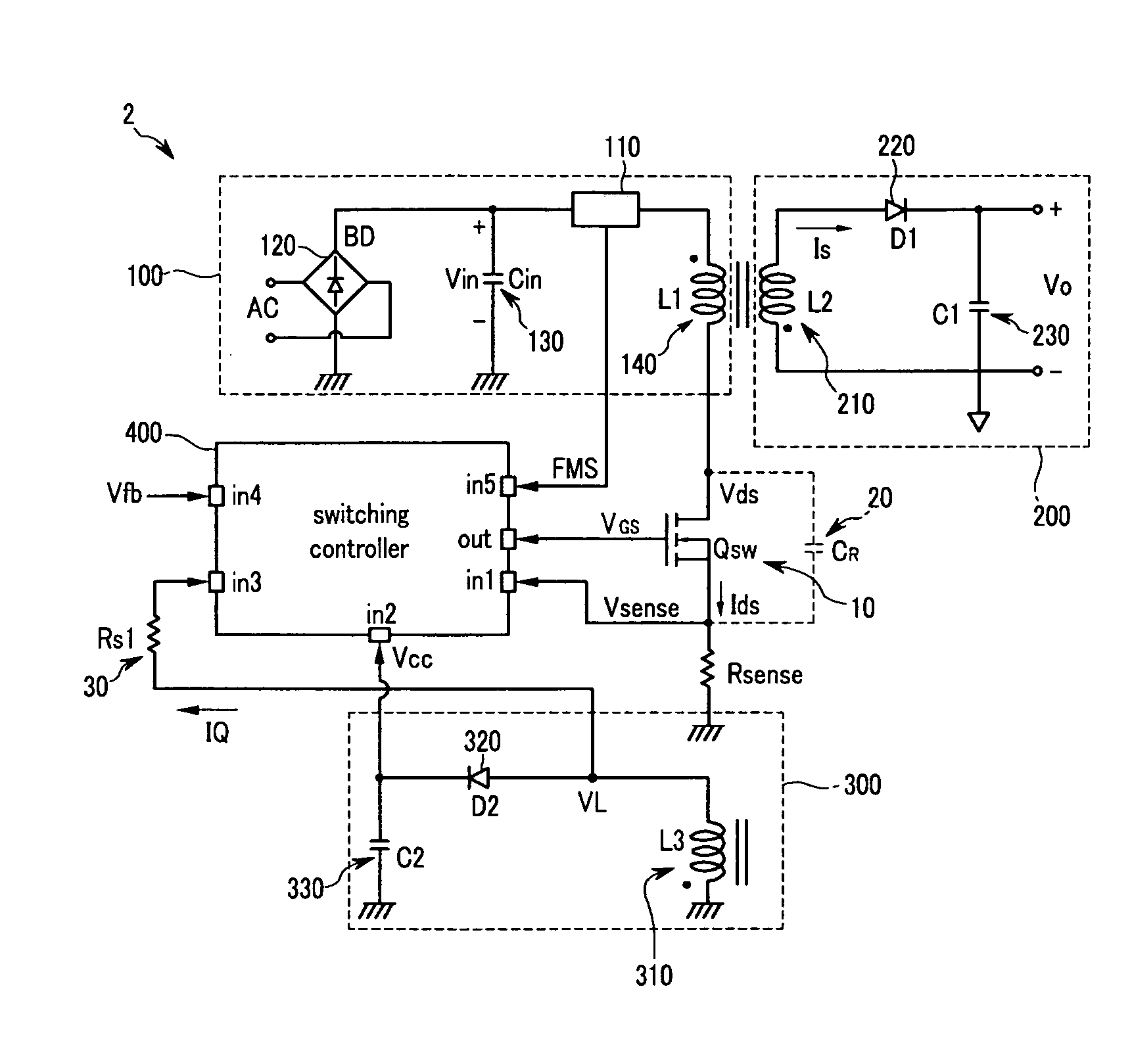
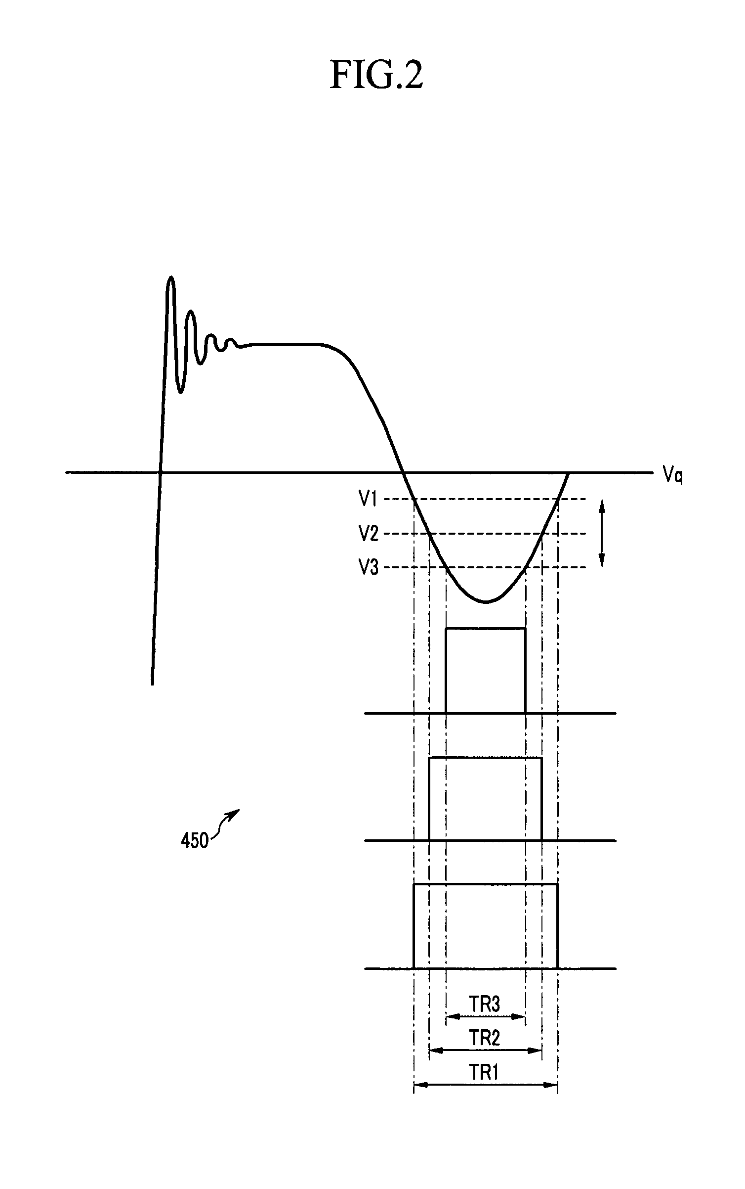
[0023]Embodiments of the present invention and their advantages are best understood by referring to FIGS. 1 through 6 of the drawings. In the following detailed description, only certain exemplary embodiments of the present invention have been shown and described, simply by way of illustration. As those skilled in the art would realize, the described embodiments may be modified in various different ways, all without departing from the spirit or scope of the present invention. Accordingly, the drawings and description are to be regarded as illustrative in nature and not restrictive. Like reference numerals designate like elements throughout the specification.

[0024]Throughout this specification and the claims that follow, when it is described that an element is “coupled” or “connected” to another element, the element may be directly coupled or connected to the other element or electrically coupled or connected to the other element through one or more other elements. In addition, unles...


PUM


Abstract

In one embodiment, an SMPS includes a rectifier for generating an input DC voltage from an input AC voltage. A switching transistor is coupled to a primary coil of a transformer for generating power which is transferred to a second side of the transformer according to an operation of the switching transistor. A switching controller receives a feedback voltage corresponding to an output voltage, a sensing signal corresponding to a current flowing through the switching transistor, and a first signal corresponding to a voltage difference between a first electrode and a second electrode of the switching transistor. The switching controller controls an on / off operation of the switching transistor. The switching controller sets a threshold period whenever the first signal has a value greater than a reference value, thereby setting a plurality of threshold periods during operation of the switching mode power supply. For each threshold period, the switching controller turns on the switching transistor at a point after a variable delay time from a previous point at which the switching transistor was turned on.

Description

CROSS-REFERENCE TO RELATED APPLICATION[0001]This application claims priority to and the benefit of Korean Patent Application No. 10-2006-0067436 filed in the Korean Intellectual Property Office on Jul. 19, 2006, the entire content of which is incorporated herein by reference.BACKGROUND OF THE INVENTION[0002](a) Field of the Invention[0003]The present invention relates to a switching mode power supply (SMPS) and, more particularly, to a quasi-resonant SMPS and a method of operation.[0004](b) Description of the Related Art[0005]In general, a SMPS has at least one switching device (e.g., a transistor) which can be switched or turned on an off to deliver or supply power to a load. A SMPS can rectify an input AC voltage to an input DC voltage (also called a DC-link voltage) and convert the input DC voltage into an output DC voltage having a different level. An SMPS can be used in electronic devices such as mobile phone chargers or laptop computer adapters.[0006]Electromagnetic interferen...

Claims


Application Information

Patent Timeline
IPC IPC(8): H02M3/335
CPCH02M1/44Y02B70/1433H02M3/33523Y02B70/10H02M3/28
Inventor CHOI, HANG-SEOKKOO, GWAN-BONCHI, JAE-HWOAN
Owner SEMICON COMPONENTS IND LLC
Learn More