Illumination optics for an optical observation device

an optical observation device and illumination optic technology, applied in optics, microscopes, measurement devices, etc., can solve the problems of inability to illuminate, observe, and observe sample fields of a relatively small size, and achieve the effect of expanding the range of angle variation

Inactive Publication Date: 2008-02-28
CARL ZEISS MIKROLMAGING
View PDF5 Cites 5 Cited by
  • Summary
  • Abstract
  • Description
  • Claims
  • Application Information

AI Technical Summary

Benefits of technology

[0013]Proceeding from this prior art, it is the primary object of the invention to provide illumination optics of the type mentioned a

Problems solved by technology

TIRF microscopy is not possible in this arrangement because the illumination bundle suffers from such large aberrations that total reflection does not occur for all b

Method used


Image

  • Illumination optics for an optical observation device
  • Illumination optics for an optical observation device

Examples


Embodiment Construction

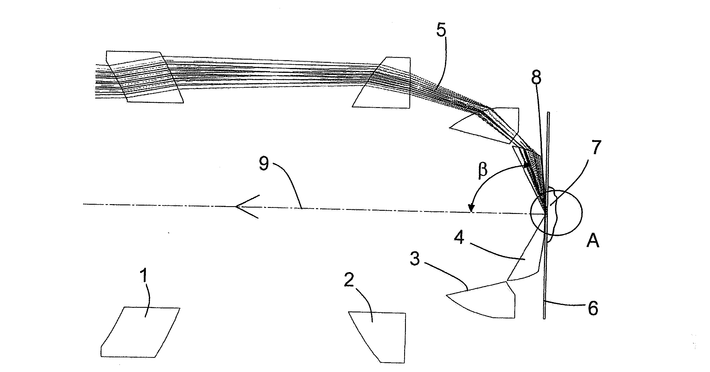
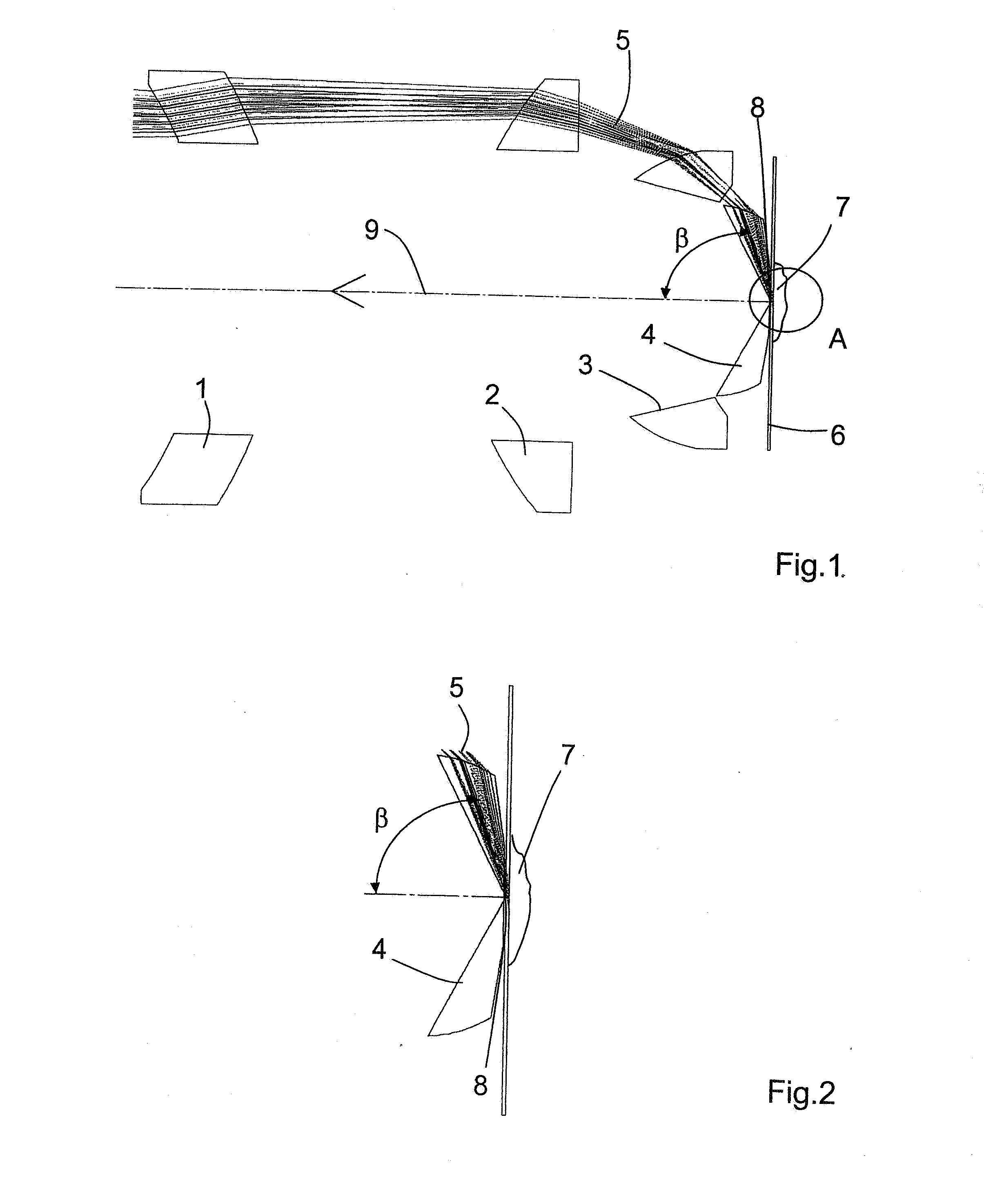
[0029]FIG. 1 shows illumination optics, according to the invention, which comprise four annular lenses 1 to 4. Lens 4 forms the front lens from which the illumination beam bundle 5 exits and strikes the interface between a carrier glass 6 and the sample 7 at an angle β which satisfies the condition of total reflection. An immersion liquid 8 is provided between the front lens 4 and the carrier glass 6.

[0030]The light coming from the sample 7 travels in a detection beam path 9 in the cut out center of the annular lenses 1 to 4 and reaches a detection device, not shown.

[0031]Lenses 1 to 4 have the radii r, thicknesses d, distances a in mm, refractive indexes ne at wavelength 546 nm, Abbe numbers ve, and free diameters Frd indicated in the following table. Contrary to the positive distances between the lenses which are otherwise only possible and conventional, negative distances or the distance 0 mm are also possible. This is easy to understand: if the drilled lens were filled to form a...


PUM


Abstract

The invention is directed to illumination optics for an optical device for observing a sample, particularly for TIRF microscopy (Total Internal Reflection Fluorescence Microscopy), wherein the sample is positioned on the side of a carrier glass remote of the illumination optics and the illumination light exiting from the illumination optics is shaped into an illumination beam bundle which encloses an angle not equal to 90° with the normal to the surface of the carrier glass. According to the invention, the illumination optics of the type mentioned above comprise at least two optically active elements which influence the shape and direction of the illumination beam bundle and which are arranged outside of the detection beam path that guides light coming from the sample to a detector. The optically active elements are preferably constructed as annular lenses and are arranged concentrically around the detection beam path.

Description

CROSS-REFERENCE TO RELATED APPLICATION[0001]This application claims priority of German Application 10 2006 039 976.5, filed Aug. 25, 2006, the complete disclosure of which is hereby incorporated by reference.BACKGROUND OF THE INVENTION[0002]a) Field of the Invention[0003]The invention is directed to illumination optics for an optical device for observing a sample, particularly for TIRF microscopy (Total Internal Reflection Fluorescence Microscopy), wherein the sample is positioned on the side of a carrier glass remote of the illumination optics and the illumination light exiting from the illumination optics is shaped into an illumination beam bundle which encloses an angle not equal to 90° with the normal to the surface of the carrier glass.[0004]b) Description of the Related Art[0005]The principle of TIRF microscopy is known, per se, from the prior art. Light coming through the carrier glass is totally reflected at the interface between the carrier glass and the sample.[0006]A cond...

Claims


Application Information

Patent Timeline
IPC IPC(8): G02B21/06
CPCG01N21/648G02B2207/113G02B21/16
Inventor BREHM, MICHAELKLEINSCHMIDT, WERNERTHIRASE, JAN
Owner CARL ZEISS MIKROLMAGING
Why Eureka
Try Eureka