Scanning type image display device
- Summary
- Abstract
- Description
- Claims
- Application Information
AI Technical Summary
Benefits of technology
Problems solved by technology
Method used
Image

Examples
first embodiment
[0090] Hereinafter, a first embodiment of the invention will be described with reference to FIGS. 1 to 3.
[0091] In the first embodiment, a description is given using as an example a laser scanning-type image display device that displays an image on a screen by scanning laser light (scanning-type image display device).
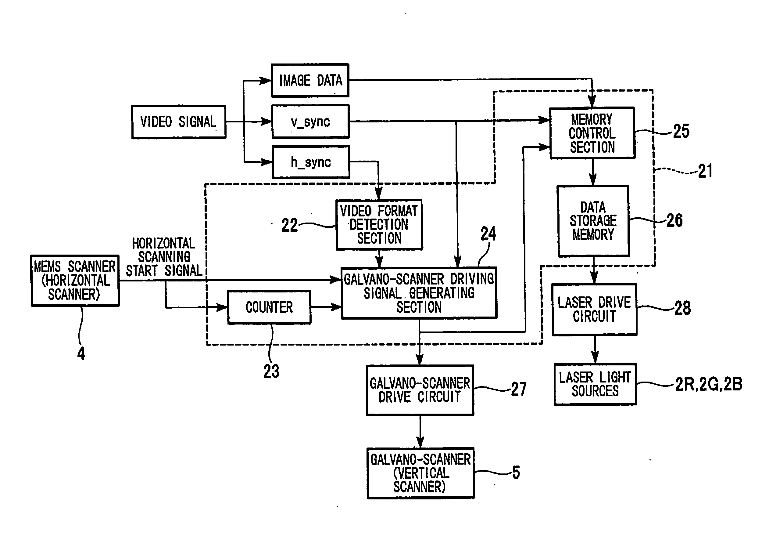
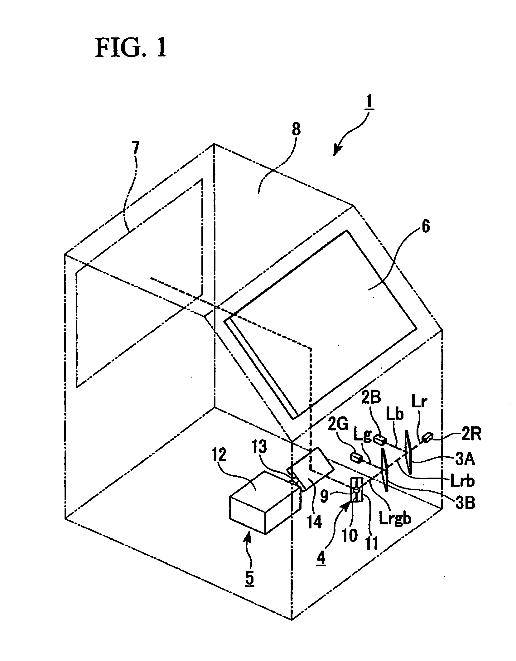
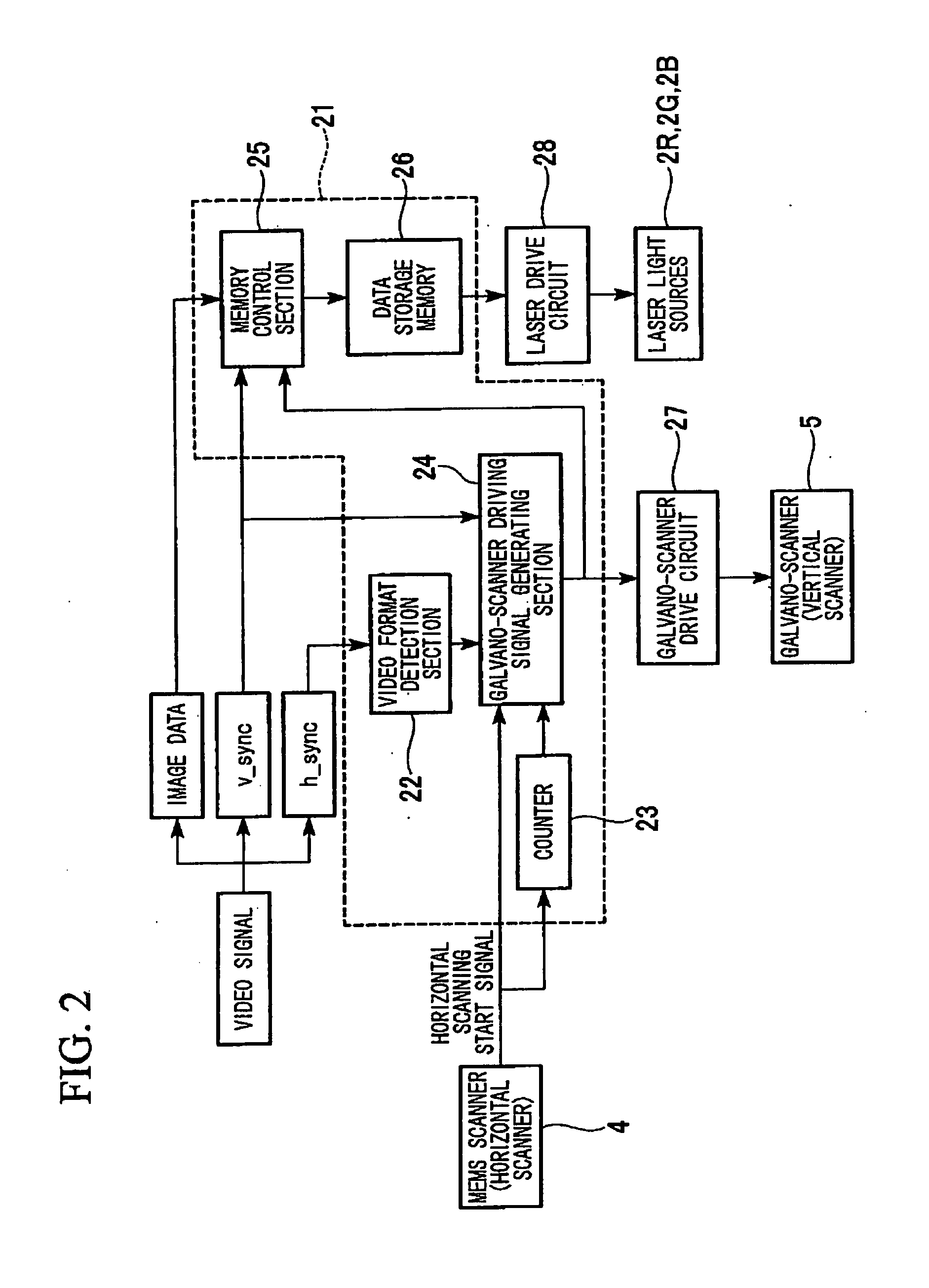
[0092]FIG. 1 is a perspective view of the main sections of the laser scanning-type image display device of the first embodiment FIG. 2 is a functional block diagram of the control section of the same device. FIG. 3 is a conceptual diagram of the method of vertical scanning in the laser scanning-type image display device.
[0093] A laser scanning-type image display device 1 (hereinafter simply referred to as an image display device) of the first embodiment includes laser light source sections 2R, 2G, and 2B (light source section), dichroic mirrors 3A and 3B, a MEMS scanner (horizontal scanner) 4, a galvano-scanner (vertical scanner) 5, a projection direction changing mi...
second embodiment
[0142] A second embodiment of the invention will be described hereinbelow.
[0143] The basic constitution of the laser scan-type image display device of the second embodiment is completely identical to the first embodiment, with only the method of vertical scanning differing from the first embodiment.
[0144] Therefore, only this point will be described with reference to FIG. 4.
[0145]FIG. 4 is a conceptual diagram of the method of vertical scanning in the laser scanning-type image display device of the second embodiment.
[0146] In the second embodiment as well, the description is made assuming similarly to the first embodiment that a video signal with a 720p video format is input to a 1080p scan system.
[0147] In the image display device 1 of the first embodiment, contraction of the image in the vertical direction was corrected by raising the vertical scanning speed 3 / 2 times.
[0148] In contrast, the image display device of the second embodiment corrects the contraction of the image ...
third embodiment
[0155] A third embodiment of the invention will be described hereinbelow.
[0156] The basic constitution of the last scan-type image display device of the third embodiment is completely identical to the first embodiment, with only the method of vertical scanning differing from the first embodiment.
[0157] Therefore, only this point will be described with reference to FIG. 5.
[0158]FIG. 5 is a conceptual diagram of the method of vertical scanning in the image display device of the third embodiment.
[0159] In the third embodiment, it is assumed that a video signal having a video format with a resolution of 480p (858×525, 60 Hz) (second video signal) that is still lower than the first embodiment is input to a 1080p scan system similarly to the first embodiment.
[0160] In the case of displaying this video format, it is sufficient for the MEMS scanner 4 to scan only 525 lines (target line number).
[0161] However, the MEMS scanner 4 actually scans 1125 lines.
[0162] As a result, the drawin...
PUM
 Abstract
Description
Claims
Application Information
 - R&D
- Intellectual Property
- Life Sciences
- Materials
- Tech Scout
- Unparalleled Data Quality
- Higher Quality Content
- 60% Fewer Hallucinations
Browse by: Latest US Patents, China's latest patents, Technical Efficacy Thesaurus, Application Domain, Technology Topic, Popular Technical Reports.
© 2025 PatSnap. All rights reserved.Legal|Privacy policy|Modern Slavery Act Transparency Statement|Sitemap|About US| Contact US: help@patsnap.com