
Modular Transportable Heating Device

a heating device and portable technology, applied in the field of modules, can solve the problems of not being able to provide warm milk, affecting the causing a great deal of trouble for the person taking care of the baby,

Inactive Publication Date: 2008-02-21
TEGLBJARG CASPER
View PDF15 Cites 88 Cited by
  • Summary
  • Abstract
  • Description
  • Claims
  • Application Information

AI Technical Summary

Benefits of technology

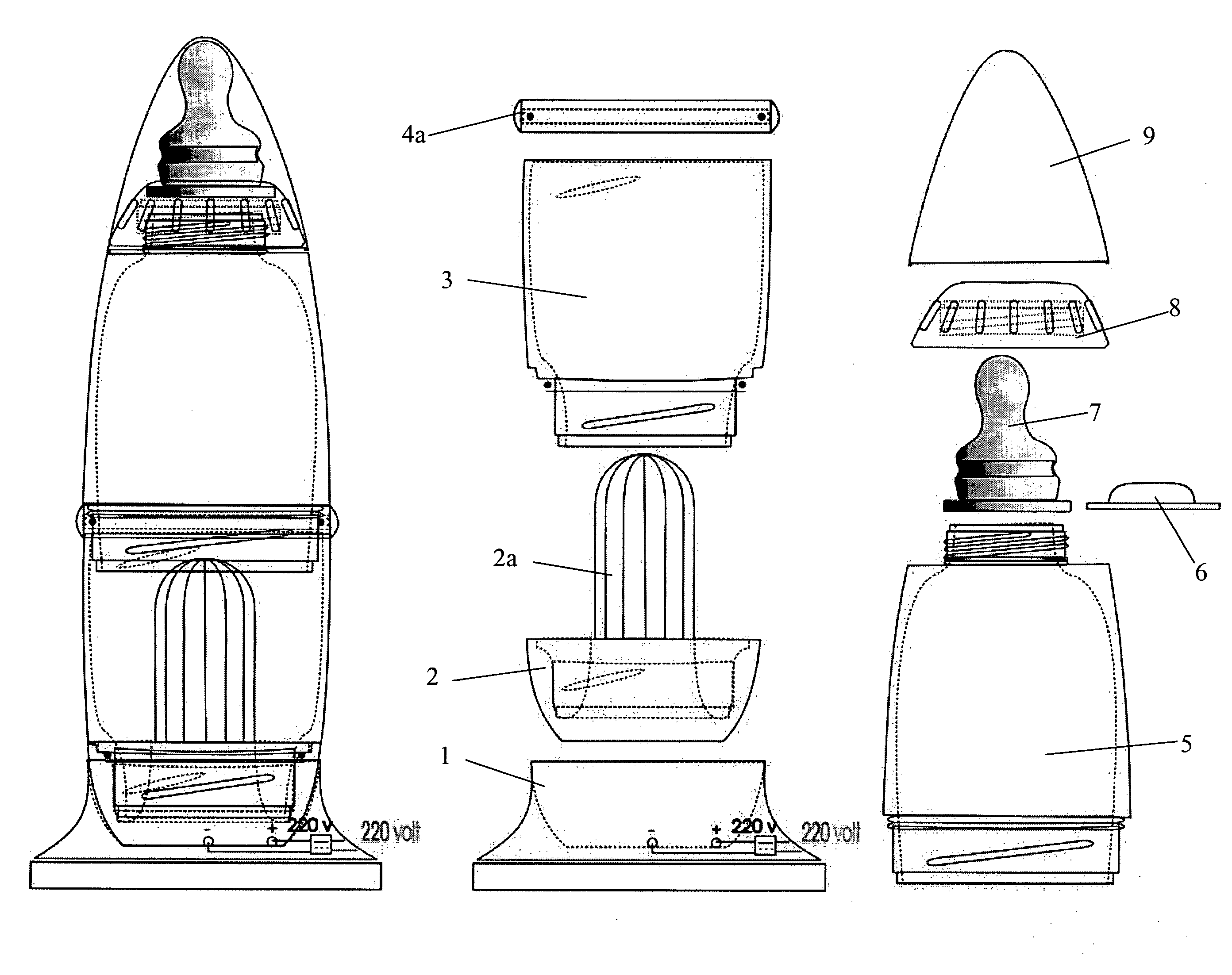
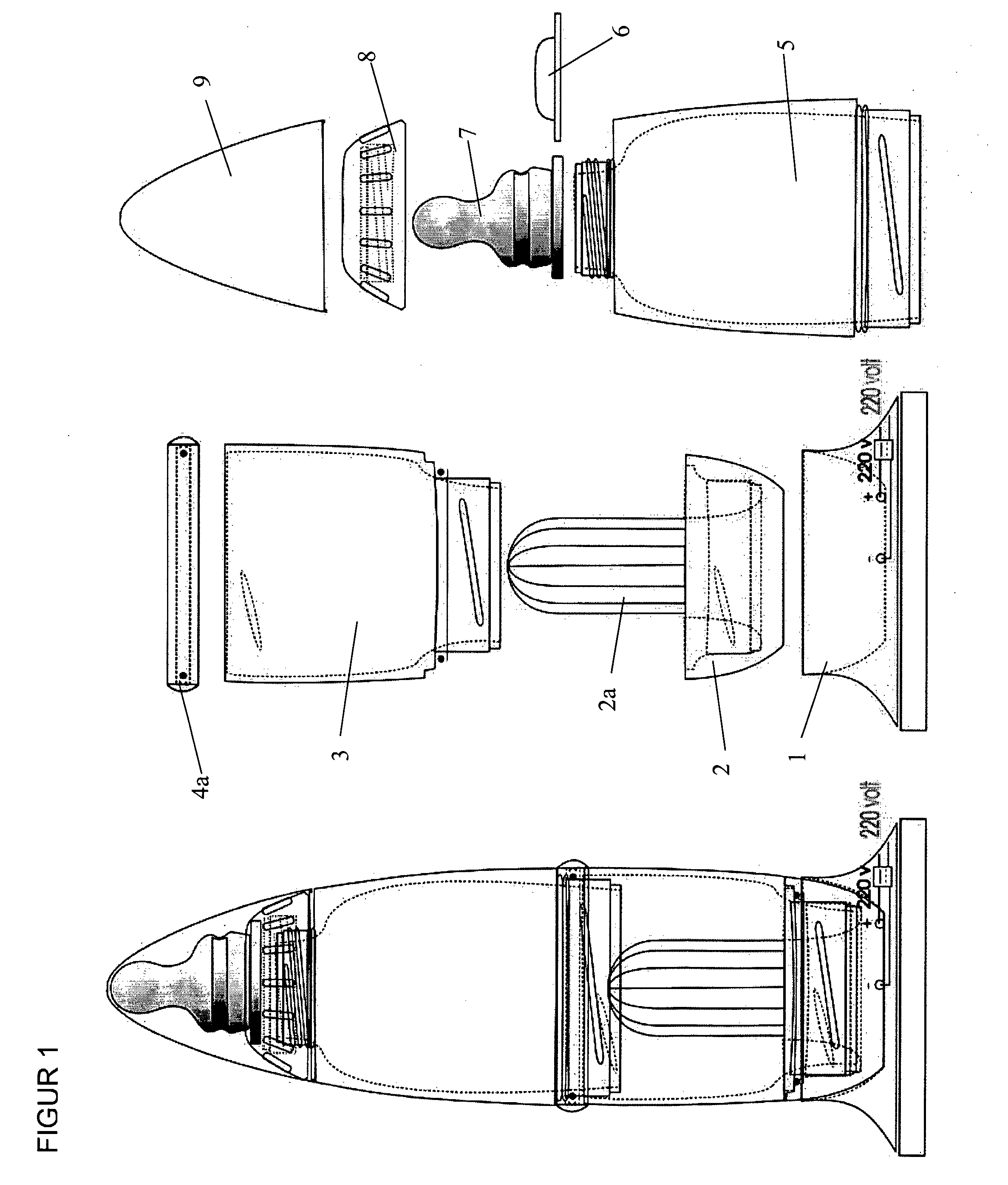
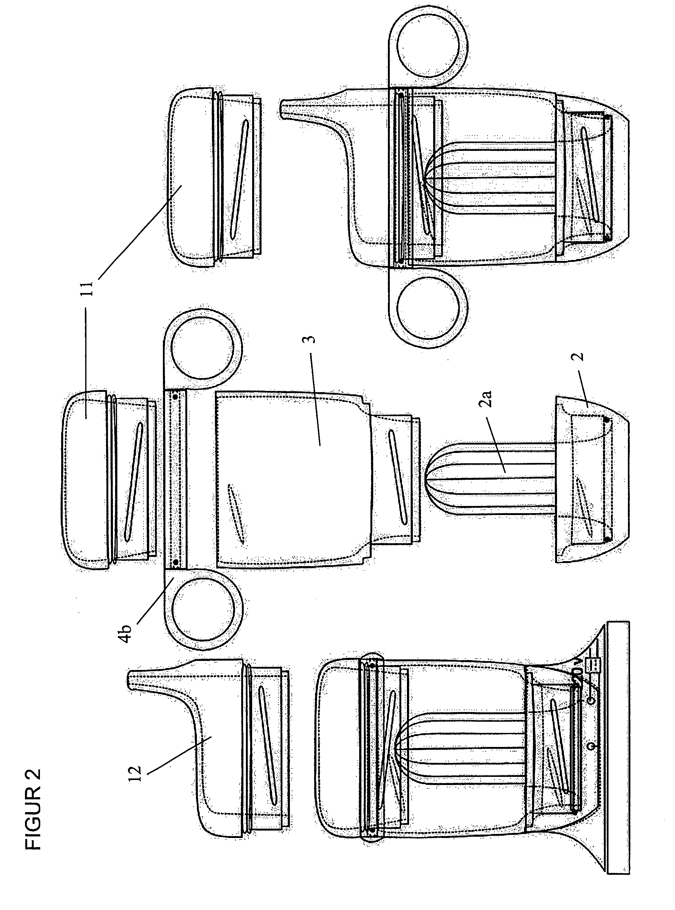
[0002]The aim of the present invention is that it should result in a container that has a cavity (e.g. cylindrical) into which a heat source can be introduced so that, through contact between the shells of the cavity and the heat source, heat can be transferred to the container and its contents. Furthermore, the heat source is to be an energy-storing cartridge that can be turned on whenever the user so wishes. Of course, it would also be possible to have variant in which, like an ordinary kettle, a heating element is in direct contact with the liquid inside the container. The previously mentioned cavity may be suitably located at the base of the container, but it is, of course, equally feasible to have the cavity along the sides, or running from the top, of the container. Here, it is convenient to attach the heating unit to the container by means of a screw thread. The heating unit can be of any suitable type whatsoever. Thus, the unit could be a battery connected to a heat-generating resistance wire. Another way of generating warmth is to use two different substances that, when mixed, give off heat. Water and calcium chloride are two possible substances here. The container itself is characterised by its modular build and the possibility of constructing different variants by combining different, shared subcomponents. This has the advantage that the manufacture of different variants (e.g. a heated coffee mug or heated feeding bottle) is greatly simplified by the fact that, to a considerable extent, the products share a common design. Furthermore, a product with several areas of application can be provided, the consumer thus not being obliged to buy a completely new apparatus for each application. Of course, the invention is not restricted to having a modular design. Modularity is simply a worthwhile property.

Problems solved by technology

This often entails a good deal of bother for the person taking care of the baby.
This can present problems when the carer wishes to go on an outing, travel somewhere or visit friends.
The concern that it may not be possible to provide warm milk for the baby may even result in the avoidance of such activities.

Method used


Image

  • Modular Transportable Heating Device
  • Modular Transportable Heating Device
  • Modular Transportable Heating Device

Examples


Embodiment Construction

[0002]The aim of the present invention is that it should result in a container that has a cavity (e.g. cylindrical) into which a heat source can be introduced so that, through contact between the shells of the cavity and the heat source, heat can be transferred to the container and its contents. Furthermore, the heat source is to be an energy-storing cartridge that can be turned on whenever the user so wishes. Of course, it would also be possible to have variant in which, like an ordinary kettle, a heating element is in direct contact with the liquid inside the container. The previously mentioned cavity may be suitably located at the base of the container, but it is, of course, equally feasible to have the cavity along the sides, or running from the top, of the container. Here, it is convenient to attach the heating unit to the container by means of a screw thread. The heating unit can be of any suitable type whatsoever. Thus, the unit could be a battery connected to a heat-generati...


PUM


Abstract

During journeys, and at other times when no stationary heating devices such as microwave ovens or hotplates are available, providing hot foods, liquid or solid, can be problematic. By providing a container with an in-built heating arrangement, the present invention solves the problem. Furthermore, the container is of a modular design. Its parts are easily interchangeable and new configurations for different purposes can be readily put together.

Description

BACKGROUND TO THE INVENTION[0001]The present invention is based on a modular, portable heating device such as a baby's feeding bottle with an in-built heat source. As a rule, one part of such a feeder is a plastic bottle, or a bottle of a different material. Using any suitable method (e.g. a screw thread) a teat can be fitted to the bottle's opening. As a rule, the feeding bottle's contents (e.g. formula milk) have to be heated before they are served to a baby. This often entails a good deal of bother for the person taking care of the baby. Two common heating methods are to place the feeding bottle in a saucepan of hot water or in a microwave oven. This can present problems when the carer wishes to go on an outing, travel somewhere or visit friends. The concern that it may not be possible to provide warm milk for the baby may even result in the avoidance of such activities. Furthermore, it is important that the contents can be heated to a specific temperature that is neither too col...

Claims


Application Information

Patent Timeline
Patent Type & Authority Applications(United States)
IPC IPC(8): B65D83/72A61J9/00A47J36/24A47J36/28A61J
CPCA47J36/2411A47J36/2433A47J36/2444A61J2200/42A47J36/28A61J9/00A47J36/2461A47J36/2472
Inventor TEGLBJARG, CASPER
Owner TEGLBJARG CASPER
Learn More