
Optical System for Measuring Metabolism in a Body, Method and Program

a technology of optical system and metabolic rate, applied in the field of optical system for measuring metabolism in the body, can solve the problems of difficult to accurately assess the presence or absence of disease, uncertain reproducibility of individual, etc., and achieve the effect of facilitating the preparation or accurate diagnosis of a effectively grasping a time-sequential change in an individual, and facilitating the preparation of the diagnosis of the change in the condition of each subj

Inactive Publication Date: 2008-02-14
HITACHI LTD
View PDF1 Cites 3 Cited by
  • Summary
  • Abstract
  • Description
  • Claims
  • Application Information

AI Technical Summary

Benefits of technology

[0015]According to the present invention, multiple different pieces of information are integrated in order to provide new information. This lightens manipulations an examining person has to perform and permits ready or accurate diagnosis.
[0016]Multiple data sets acquired at different time instants by measuring the same subject are integrated, and the resultant information is presented to an examining person in an easy-to-understand manner. Ready diagnosis of a change in the condition of each subject can be aided.
[0017]Moreover, since the present invention makes it possible to effectively grasp a time-sequential change in an individual, it can be applied to evaluation of the results of rehabilitation or image training or diagnosis.

Problems solved by technology

However, the reproducibility in an individual is uncertain.
It is not easy to accurately assess the presence or absence of a disease in each subject or the symptom thereof.

Method used


Image

  • Optical System for Measuring Metabolism in a Body, Method and Program
  • Optical System for Measuring Metabolism in a Body, Method and Program
  • Optical System for Measuring Metabolism in a Body, Method and Program

Examples


Embodiment Construction

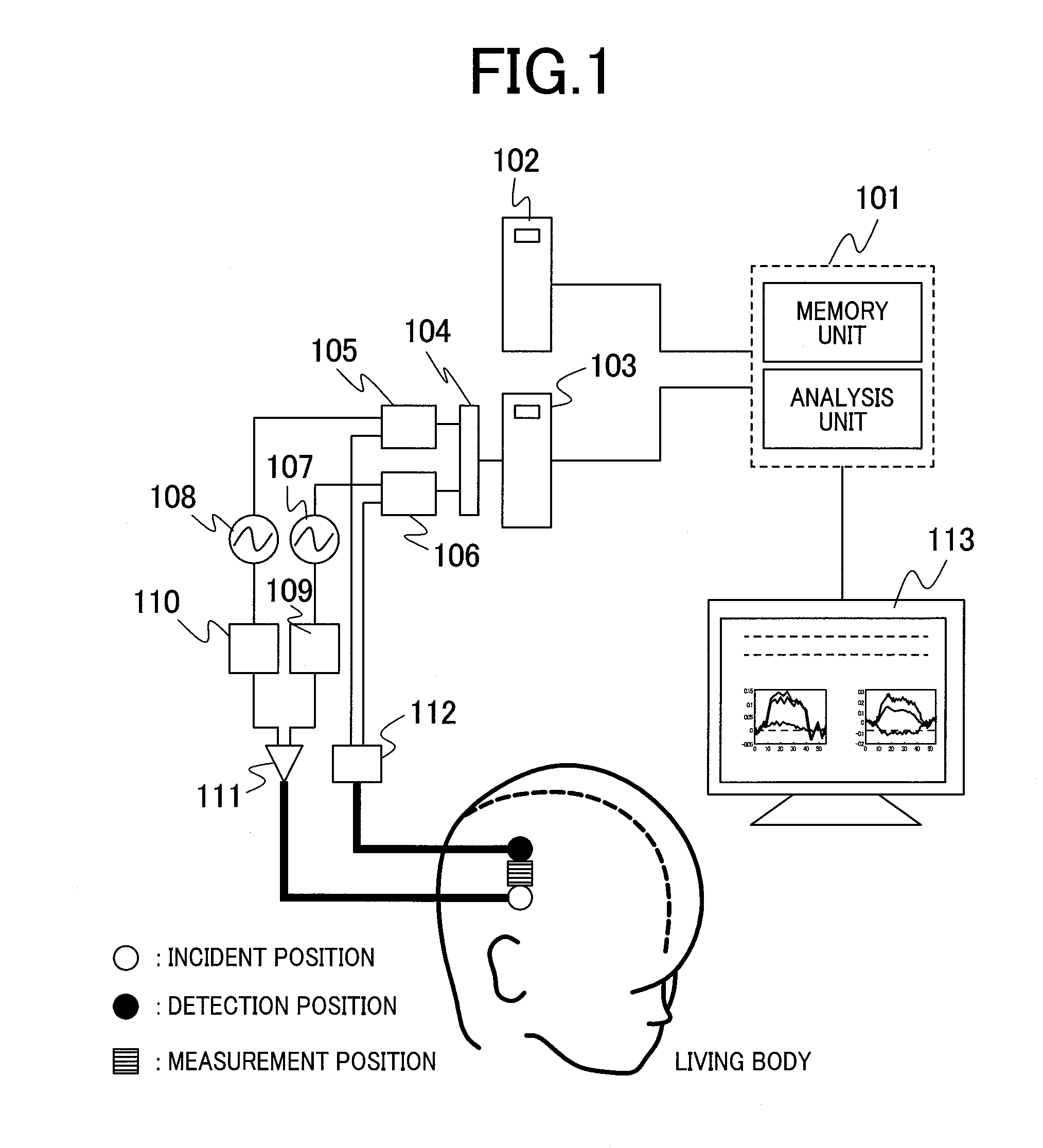
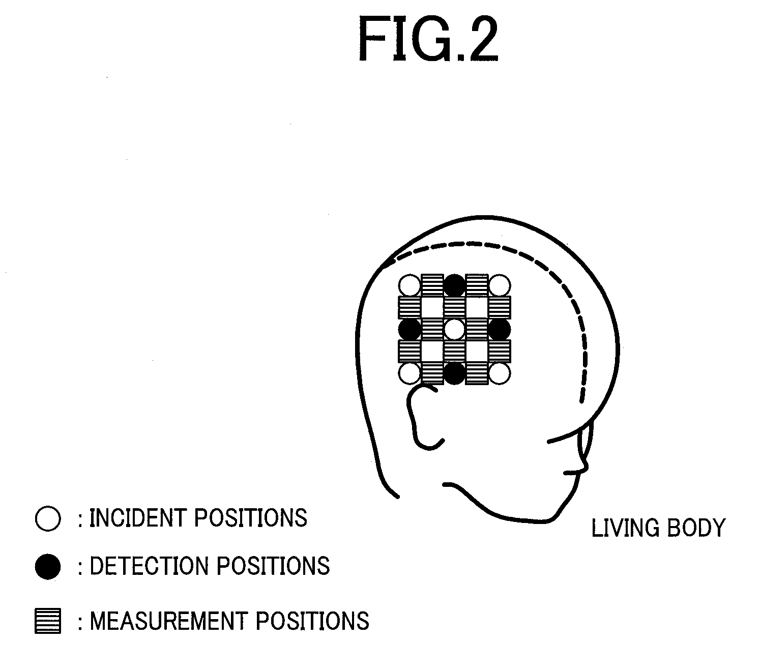
[0030]Referring to the drawings, an embodiment of the present invention will be described below. FIG. 1 is a block diagram showing the outline of an optical organism measurement system in accordance with the present invention. The optical organism measurement system includes: a control unit 103 realized with an electronic computer represented by a personal computer or a workstation; two laser diodes 109 and 110 offering mutually different wavelengths; oscillators 107 and 108 that produce signals with which light waves produced by the two laser diodes are modulated at different frequencies; an optical mixer 110 that mixes two light waves having different peak wavelengths; a light irradiation means for irradiating light, which is produced by the optical mixer 110, to a light incident position on a living body over an optical fiber; a photodetector 111 that detects mixed light at a light-detected position (approximately 3 cm away in this embodiment) appropriately separated from the lig...


PUM


Abstract

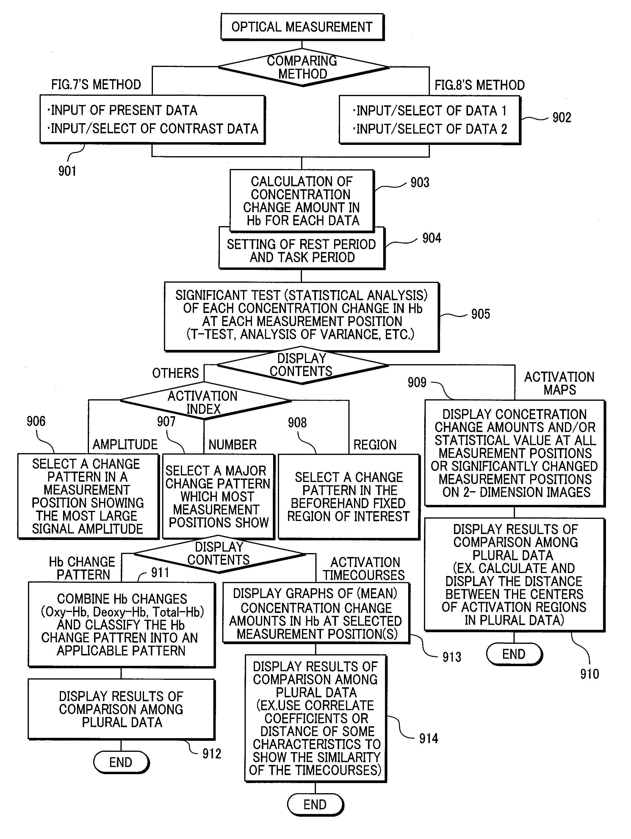
In the past, comparison of mean values or variances measured from multiple subjects with one another has been a mainstream of diagnostic support to be achieved using cerebral activity signals. However, in this case, it is hard to absorb individual differences, and the precision in a diagnostic support technology is low. In order to improve the precision in the diagnostic support technology, the property of data acquired by an optical organism measurement system is utilized in order to create and display information representing a change in the condition of each person. Thus, diagnosis of each person is effectively supported. Measured light signals are used to calculate and record changes in the concentrations of oxidized hemoglobin (Hb), deoxidized Hb, and total Hb respectively. Based on each data (representing the Hb concentration changes), two or more Hb concentration changes (for example, the oxidized Hb concentration change and deoxidized Hb concentration change) are classified according to whether the changes are increases or decreases, and indicated in the form of symbols, an image, or a graph. Thus, an examining person is provided with compressed and simplified information and supported in diagnosis.

Description

TECHNICAL FIELD[0001]The present invention relates to an optical organism measurement system that optically measures intracorporeal information, or especially, a change in the concentration of an optically absorbent material. More particularly, the present invention is concerned with an optical organism measurement system that uses data, which is obtained through optical organism measurement, to provide information that aids in assessing fitness.BACKGROUND ART[0002]The employment of light that is highly transmissive by an organism and exhibits a peak in light intensity in a wavelength band ranging from a visible region to a near-infrared region permits noninvasive measurement of intracorporeal information. This is attributable to the Lambert-Beer's law defining that a logarithmic value representing a measured light signal is proportional to the product of an optical length by a concentration. A technology of evolving the law and measuring a relative change in the concentration of in...

Claims


Application Information

Patent Timeline
Patent Type & Authority Applications(United States)
IPC IPC(8): G06F19/00A61B5/00A61B5/145A61B10/00
CPCA61B5/0059G06F19/3406A61B5/7264A61B5/7425A61B5/743G16H40/63
Inventor SATO, HIROKIMAKI, ATSUSHIYAMAMOTO, TSUYOSHIKIGUCHI, MASASHI
Owner HITACHI LTD
Learn More