
Method for routing information over a network employing centralized control

a network and information routing technology, applied in the field of information networks, can solve the problems of inefficiency in capacity allocation, inability to scale well for large data networks, and most failures are transparent to the end user, and achieve the effects of efficient bandwidth usage, fast restoration, and simple provisioning

Inactive Publication Date: 2008-02-14
CISCO TECH INC
View PDF11 Cites 36 Cited by
  • Summary
  • Abstract
  • Description
  • Claims
  • Application Information

AI Technical Summary

Benefits of technology

[0012] Embodiments of the present invention provide a centralized routing protocol that supports relatively simple provisioning and relatively fast restoration (on the order of, for example, 50 ms), while providing relatively efficient bandwidth usage (i.e., minimizing excess bandwidth requirements for restoration, on the order of less than 100% redundant capacity and preferably less than 50% redundant capacity). Such a centralized routing protocol is, in certain embodiments, easily scaled to accommodate increasing bandwidth requirements.
[0013] According to embodiments of the present invention, an apparatus and method are described for configuring routes over a network. Such a method, embodied in a protocol according to embodiments of the present invention, provides several advantages, including relatively fast restoration (on the order of, for example, 50 ms) and relatively efficient bandwidth usage (i.e., on the order of less than 100% redundant capacity and preferably less than 50% redundant capacity).

Problems solved by technology

Two approaches in common use today are diverse protection and self-healing rings (SHR), both of which offer relatively fast restoration times with relatively simple control logic, but do not scale well for large data networks.
This is mostly due to their inefficiency in capacity allocation.
Their fast restoration time, however, makes most failures transparent to the end-user, which is important in applications such as telephony and other voice communications.
These alarms are undesirable because such alarms usually result in dropped calls, causing users down time aggravation.
Restoration times that exceed 10 seconds can lead to timeouts at higher protocol layers, while those that exceed 1 minute can lead to disastrous results for the entire network.
However, the price of such quickly restored information flow is the high bandwidth requirements of such systems.
However, restoration times exhibited by such approaches range from several minutes to several months.

Method used


Image

  • Method for routing information over a network employing centralized control
  • Method for routing information over a network employing centralized control
  • Method for routing information over a network employing centralized control

Examples


Embodiment Construction

[0047] The following is intended to provide a detailed description of an example of the invention and should not be taken to be limiting of the invention itself. Rather, any number of variations may fall within the scope of the invention which is defined in the claims following the description.

Network Architecture

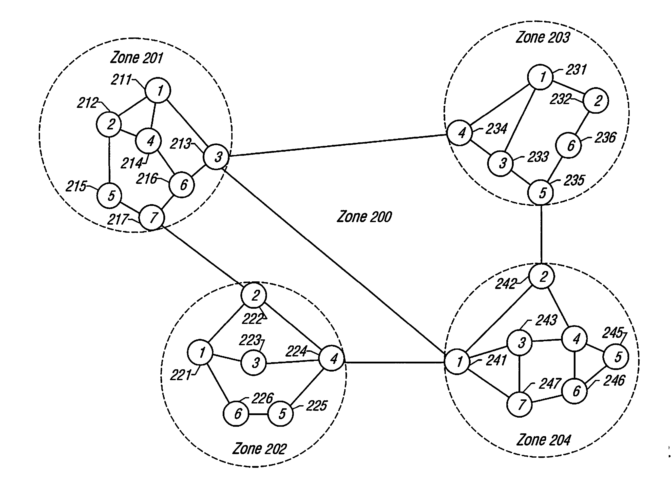
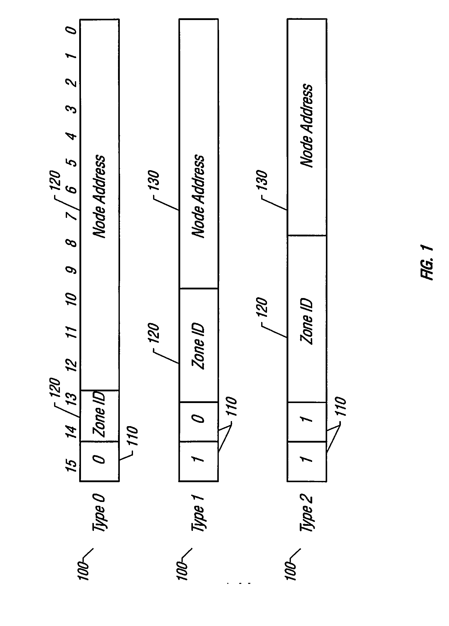
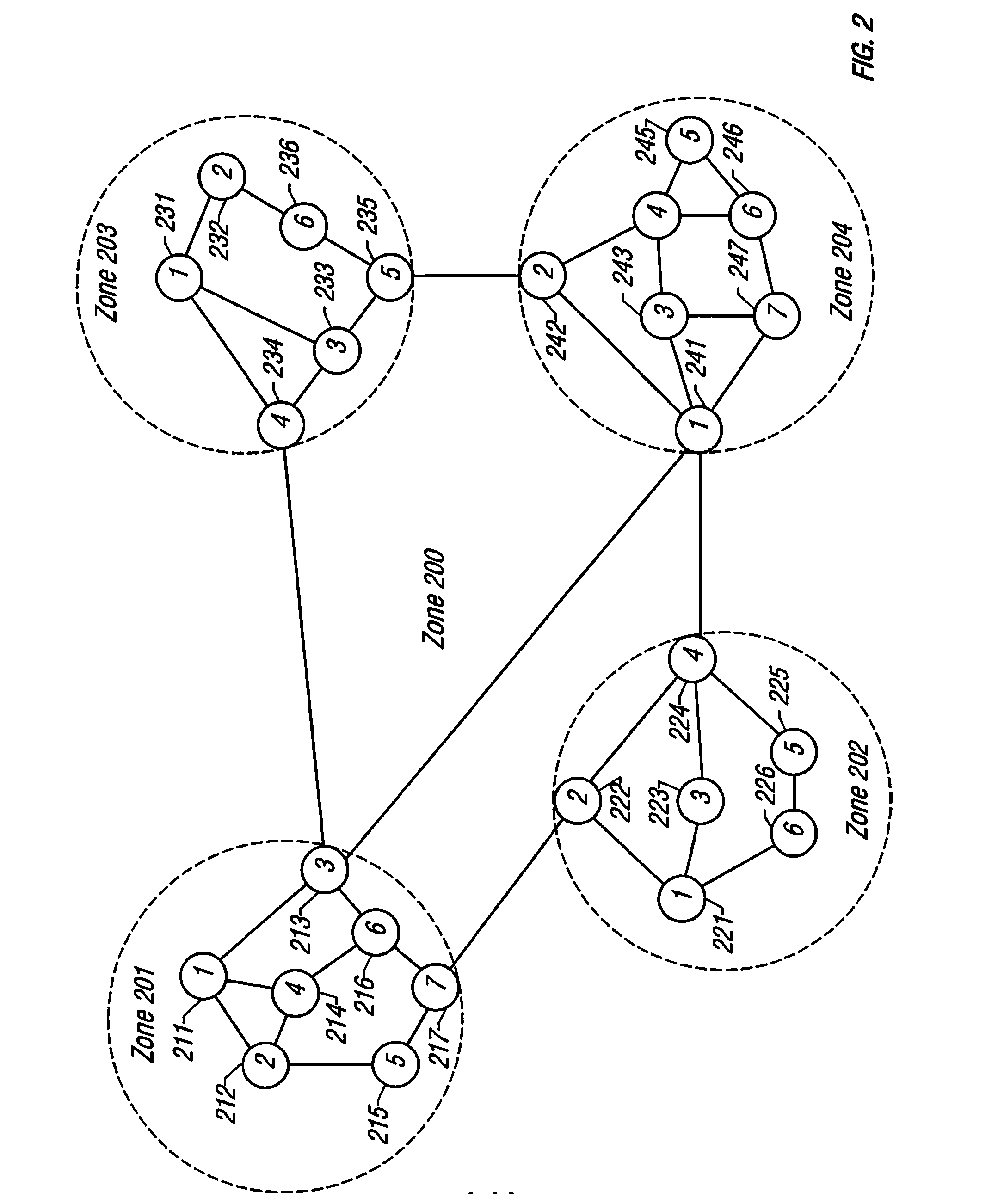
[0048] To limit the size of the topology database and the scope of broadcast packets, networks employing an embodiment of the protocol described herein can be divided into smaller logical groups referred to herein as “zones.” Each zone runs a separate copy of the topology distribution algorithm, and nodes within each zone are only required to maintain information about their own zone. There is no need for a zone's topology to be known outside its boundaries, and nodes within a zone need not be aware of the network's topology external to their respective zones.

[0049] Nodes that attach to multiple zones are referred to herein as border nodes. Border nodes are required to ...


PUM


Abstract

A method and apparatus for centralized control of a network is described. The network includes a number of nodes. The method includes creating a database and storing the database on a master node of the network. The database contains topology information regarding a topology of the network. Each of the nodes is coupled to at least one other of the nodes, with the master node being one of the nodes.

Description

CROSS-REFERENCES TO RELATED APPLICATIONS [0001] This application is a divisional of U.S. patent application Ser. No. 11 / 290,261, now U.S. Pat. No. 7,286,490, entitled “A Method for Routing Information over a Network Employing Centralized Control,” issued on Oct. 23, 2007, and naming Ali N. Saleh, H. Michael Zadikian, Zareh Baghdasarian and Vahid Parsi as inventors, which is a divisional of U.S. Pat. No. 6,973,023, entitled “A Method for Routing Information over a Network Employing Centralized Control,” issued on Dec. 6, 2005, and naming Ali N. Saleh, H. Michael Zadikian, Zareh Baghdasarian and Vahid Parsi as inventors, which in turn, is related to U.S. Pat. No. 6,856,627, issued on Feb. 15, 2005, entitled “A METHOD FOR ROUTING INFORMATION OVER A NETWORK,” and U.S. Pat. No. 6,724,757, issued on Apr. 20, 2004, entitled “A CONFIGURABLE NETWORK ROUTER.” These applications are hereby incorporated by reference, in their entirety and for all purposes.BACKGROUND OF THE INVENTION [0002] 1. F...

Claims


Application Information

Patent Timeline
Patent Type & Authority Applications(United States)
IPC IPC(8): H04L12/28H04J3/14H04L12/24
CPCH04L12/66H04L41/12H04L41/0866H04L41/0803H04L41/122
Inventor SALEH, ALINZADIKIAN, H. MICHAELBAGHDASARIAN, ZAREHPARSI, VAHID
Owner CISCO TECH INC
Learn More