
Meter flow conditioner

a flow conditioner and flow rate technology, applied in the direction of liquid/fluent solid measurement, volume metering, instruments, etc., can solve the problems of inaccurate reading of meters, turbulence, and inaccurate flow characteristics

Active Publication Date: 2008-02-14
KOMAX SYST
View PDF11 Cites 40 Cited by
  • Summary
  • Abstract
  • Description
  • Claims
  • Application Information

AI Technical Summary

Benefits of technology

"The present invention is about a device that improves the flow of fluid in a pipe. It includes a mixing element and a plate with openings that help the fluid pass through. This device can be placed before the pipe to change the way the fluid flows."

Problems solved by technology

With virtually all of these technologies, it can only be as accurate as the particular flow characteristics of an incoming fluid stream.
Turbulence, in its numerous forms, causes these meters to have inaccurate readings.
Knowing that turbulence is induced by upstream disturbances caused by such things as pipe elbows, valves, restrictions, diameter reductions and the like suffer inaccuracy as a consequence.
However, this does not totally eliminate the velocity profile.
It has been found that this method is inconsistent at best and does not adequately prepare the flow for a uniform approach to the meter.
As crude prices exceeds $70 a barrel, flow meters which even have the slightest degree of inaccuracy can result in mismeasurements costing many dollars in losses.

Method used


Image

  • Meter flow conditioner
  • Meter flow conditioner
  • Meter flow conditioner

Examples


Embodiment Construction

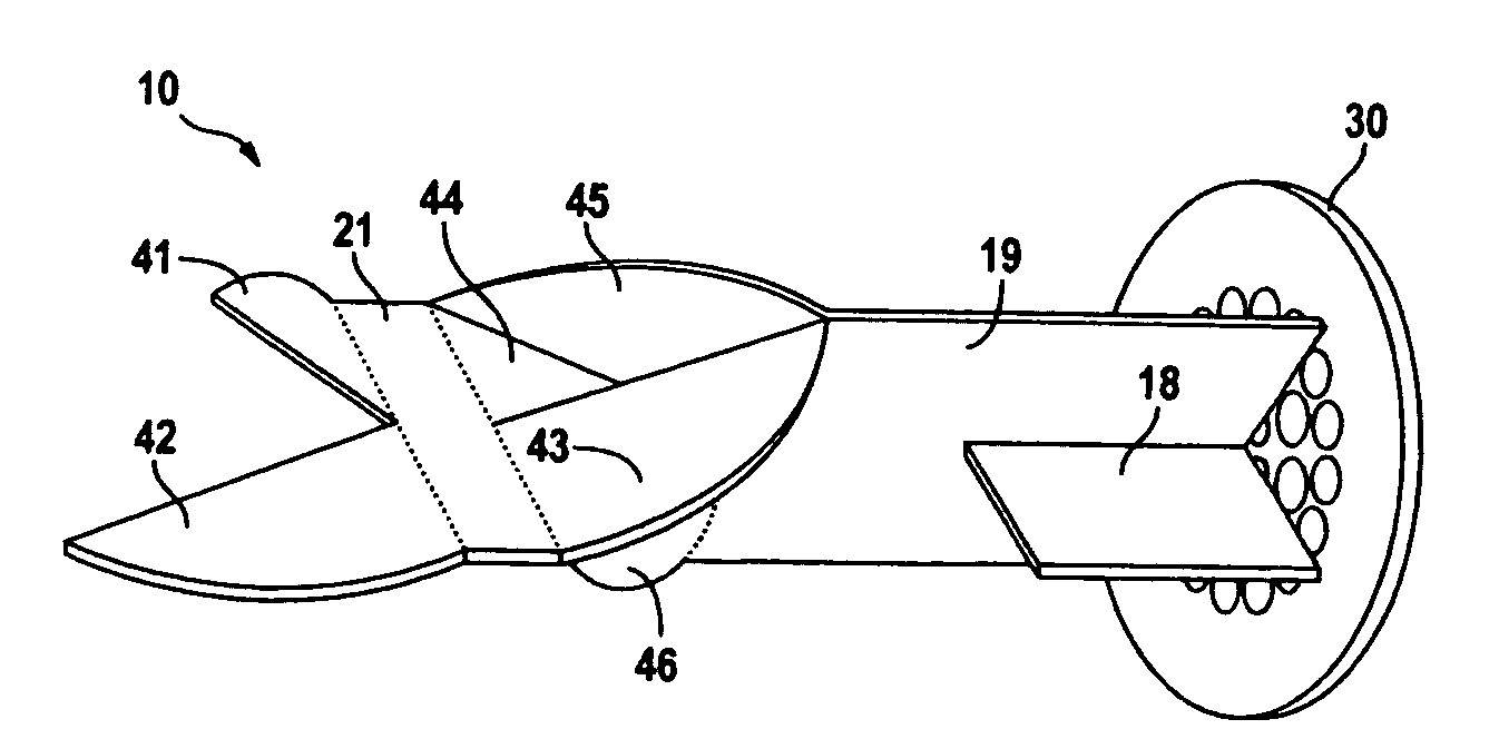
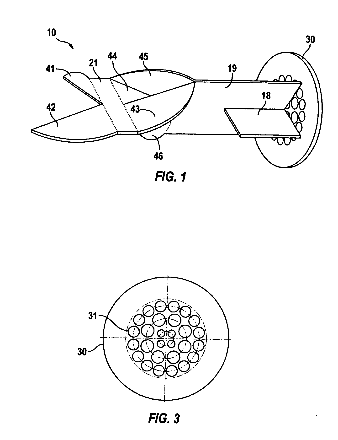
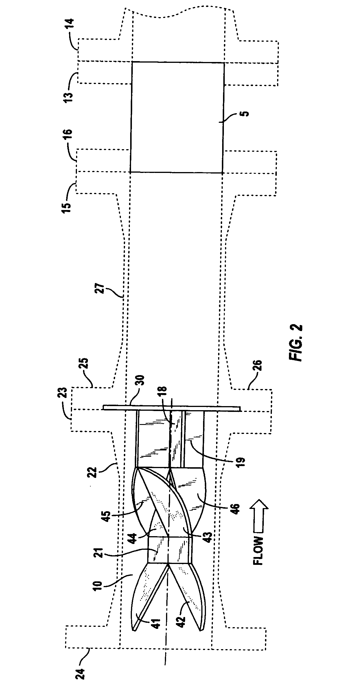
[0015]The present invention is directed to a flow conditioner in the form of a static mixer and straightener plate positioned upstream of a flow meter whose accuracy is improved thereby. Any number of static mixers can be employed in the practice of the present invention. As a means of describing this invention and as disclosing its preferred embodiment, the static mixer shown in detail in FIGS. 1 and 2 is presented. Again, although the static mixer described below represents the preferred embodiment of this invention, other static mixers, such as the static mixer described in applicant's U.S. Pat. No. 3,923,288, the disclosure of which is incorporated herein by reference, can be used.

[0016]Turning first to FIGS. 1 and 2, flow conditioner 10 is depicted. Specifically, preferred flow conditioner 10 is provided with a flat generally rectangular central portion 21 and first and second sets of ears 41, 42, 43 and 44 fixed to opposite sides of central portion 21. Each pair of ears locate...


PUM


Abstract

A fluid conditioner for a fluid traveling through a conduit, the conduit having a longitudinal axis and substantially circular cross-section. The fluid conditioner includes a static mixing element and a straightener plate. The preferred static mixer is one having a flat generally rectangular central portion having first and second sets of ears affixed on opposite sides of the central portion. The sets of ears include first and second ears bent respectively in upward and downward directions relative to the plane of the central portion wherein each pair of ears located diagonally opposite one another across the central portion are bent in the same direction relative to the plane of the central portion. A third set of ears extend from the central portion and terminate at a substantially rectangular member whose plane of orientation is substantially perpendicular to the central portion and a plate affixed to the substantially rectangular member and oriented substantially perpendicularly to the longitudinal axis of the conduit, the plate substantially covering the cross-section of the conduit having a plurality of openings to facilitate the passage of the fluid within the conduit.

Description

TECHNICAL FIELD OF INVENTION[0001]The present invention involves a fluid conditioner for use in a conduit carrying liquids or gases. The present fluid conditioner is ideally suited for use upstream of a flow meter to increase accurate flow rate readings.[0002]The present invention relates generally to a material distribution mixing apparatus acting as a flow conditioner for fluid traveling through a conduit. The present invention has particular applicability in its employment in conjunction with a flow meter being able to improve fluid flow in a pipeline to provide a swirl-free fluid condition for a flow meter to improve accuracy.BACKGROUND OF THE INVENTION[0003]Fluid flow meters have been employed in a wide variety of environments and applications. In addition, a plethora of technologies have been implemented in creating appropriate flow meters for every possible fluid measurement including differential pressure flow meters including, for example, flow nozzles, orifice plates, vent...

Claims


Application Information

Patent Timeline
Patent Type & Authority Applications(United States)
IPC IPC(8): F15D1/04
CPCG01F15/00F15D1/001
Inventor SMITH, ROBERT
Owner KOMAX SYST
Learn More