
Power Tool Case

Inactive Publication Date: 2008-02-14
COLLISTER KENNETH F +1
View PDF2 Cites 86 Cited by
  • Summary
  • Abstract
  • Description
  • Claims
  • Application Information

AI Technical Summary

Problems solved by technology

Although most batteries today will power a tool for several hours, often the batteries will require recharging on a work site during long periods of use.

Method used


Image

  • Power Tool Case
  • Power Tool Case
  • Power Tool Case

Examples


Embodiment Construction

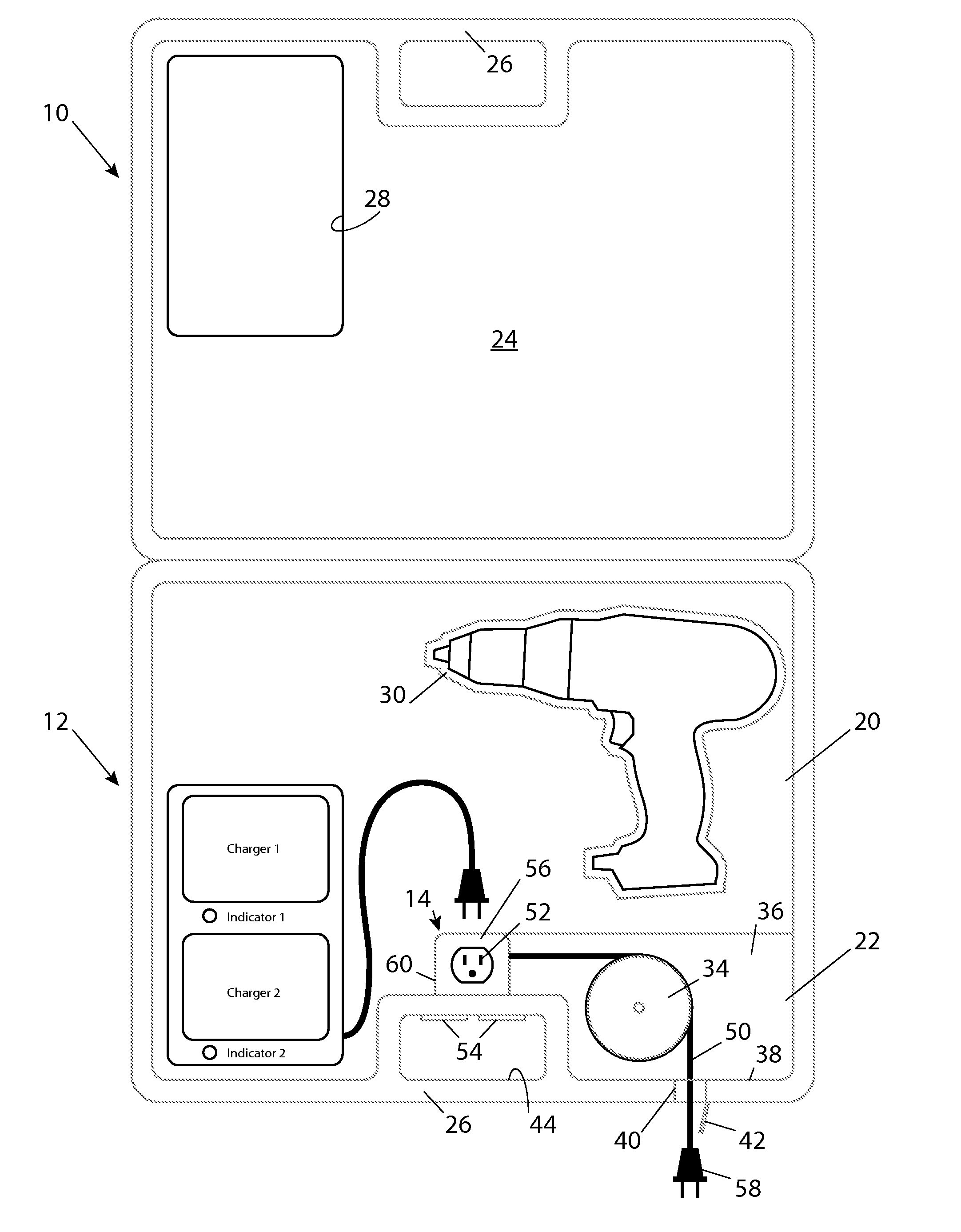
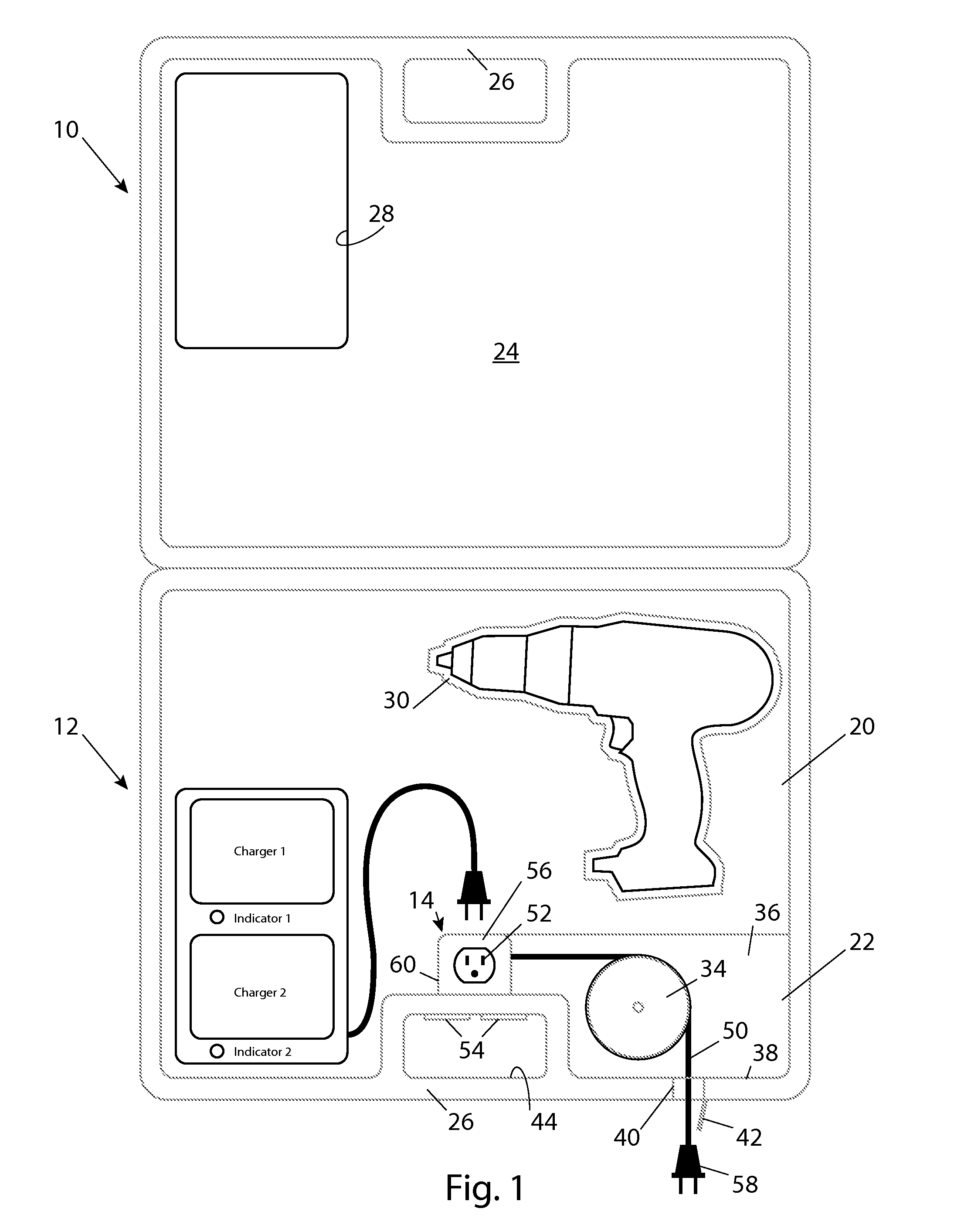
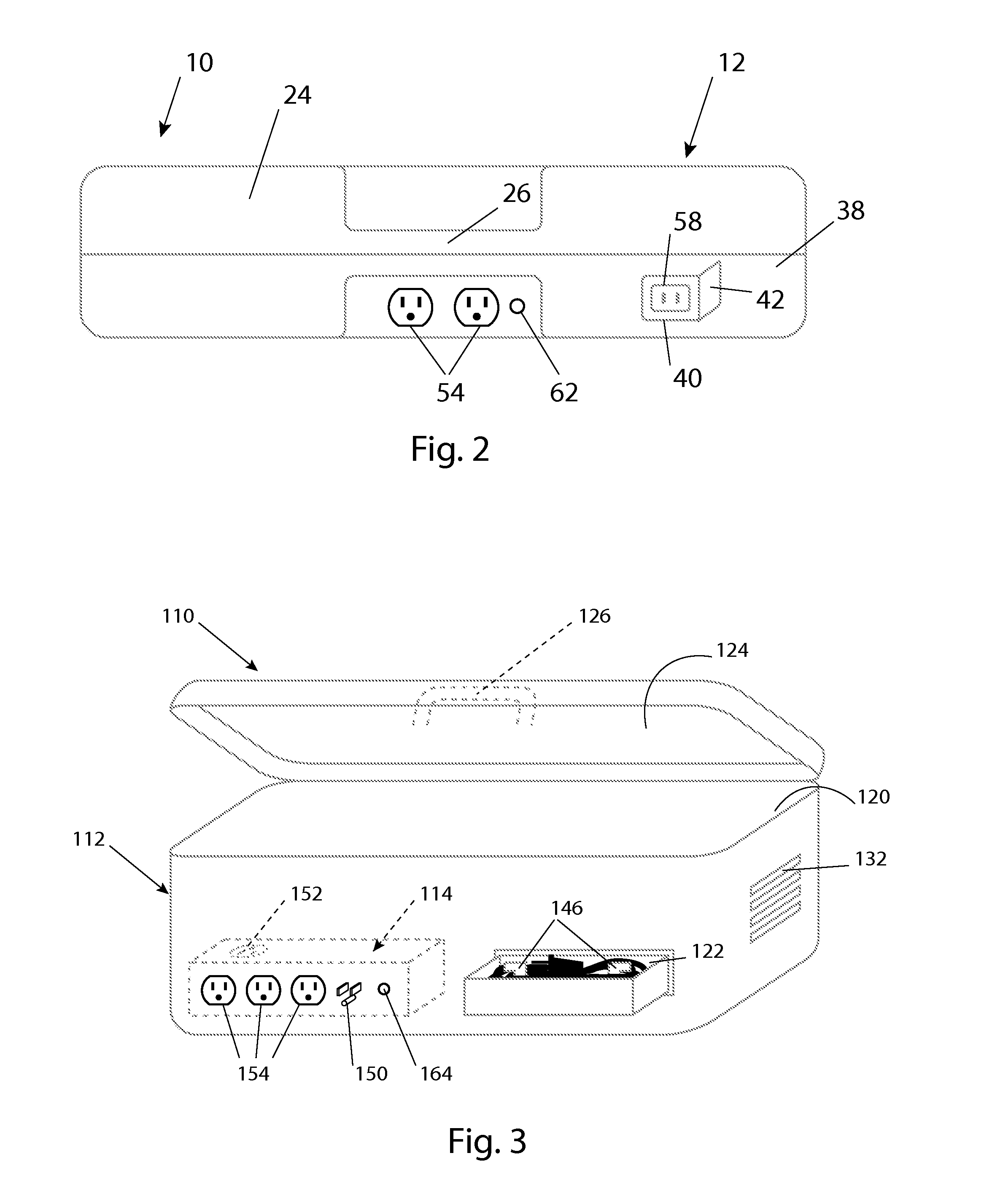
[0012]The drawings show a power tool case generally shown at 10 for storing battery-operated power tools. The case 10 is adapted for storing and transporting power tools and their accessories, such as rechargeable batteries and battery chargers. The simplest embodiments of the power tool case 10 include a housing generally indicated at 12 and electrical circuitry generally indicated at 14. The housing 12 includes at least one compartment for storing the power tool and for storing a battery charger. The housing 12 can be constructed from plastic, metal, wood, canvas, vinyl, or any other suitable material and may be sized to allow it to be easily carried by hand. The electrical circuitry 14 provides power for the case 10 to power the battery charger.

[0013]FIG. 1 shows one embodiment of the power tool case 10. The housing 12 includes a first compartment 20 for storing the battery charger, a second compartment 22 for storing a power cord, a lid 24, a handle 26, and a visual device 28. T...


PUM


Abstract

A power tool case for storing battery-operated power tools includes a housing, an electrical connector, and an internal electrical outlet. The housing defines at least one compartment for storing a battery charger and has a handle for transporting the case. The electrical connector is carried by the housing and is adapted to electrically couple with an electrical power source to provide power for the case. The internal electrical outlet is also carried by the housing and is electrically coupled with the electrical connector to allow the battery charger to remain plugged into the internal electrical outlet while the battery charger is stored in the compartment.

Description

RELATED APPLICATIONS[0001]This application claims priority to U.S. Provisional Patent Application 60 / 822,262, filed Aug. 14, 2006, the teachings of which are incorporated herein by reference.TECHNICAL FIELD[0002]This invention relates to cases for storing power tools, and more particularly to cases for storing battery-operated power tools.BACKGROUND OF THE INVENTION[0003]Battery-operated power tools often are sold in kits containing a power tool, a rechargeable battery, a battery charger, and a storage case. The battery charger typically plugs into standard electrical outlets to provide alternating current (AC) to the battery charger. The battery charger converts the AC current into direct current (DC) to charge the batteries. Although most batteries today will power a tool for several hours, often the batteries will require recharging on a work site during long periods of use. Having a standardized plug on the battery charger allows it to be plugged into any standard electrical out...

Claims


Application Information

Patent Timeline
Patent Type & Authority Applications(United States)
IPC IPC(8): A45C11/00A45C13/02B65D85/86
CPCA45C13/02B25H3/006A45C15/00
Inventor COLLISTER, KENNETH F.JONES, BRENDEN J.
Owner COLLISTER KENNETH F
Learn More