
Inspection apparatus

Inactive Publication Date: 2008-02-07
YOKOGAWA ELECTRIC CORP
View PDF5 Cites 18 Cited by
  • Summary
  • Abstract
  • Description
  • Claims
  • Application Information

AI Technical Summary

Benefits of technology

[0071]According to the present invention, since the housing is sealed air-tight from the outside air, and the housing is a safety cabinet in which the sterilization filter is provided to the outlet passage that communicates from the inside of the housing to the external, inspection can be conducted in a state where source of infection such as a pathogen and hazardous inspection samples are completely blocked. In addition, since the liquid feeding device conduct the inspection automatically, inspection is automated and the apparatus can be downsized. Accordingly, inspection can be conducted rapidly and easily.

Problems solved by technology

However, no matter how highly the worker is skilled in handling the pathogen, aerosol infection, splash infection and the like cannot be prevented without special care and facilities.
Further, since such apparatus is furnished in a region where it is managed (controlled) in accordance with bio-safety levels, there is a problem that inspection without time lapse, such as in a case where inspection is conducted on the scene where a specimen is collected from a patient, cannot be managed.

Method used


Image

  • Inspection apparatus
  • Inspection apparatus
  • Inspection apparatus

Examples


first embodiment

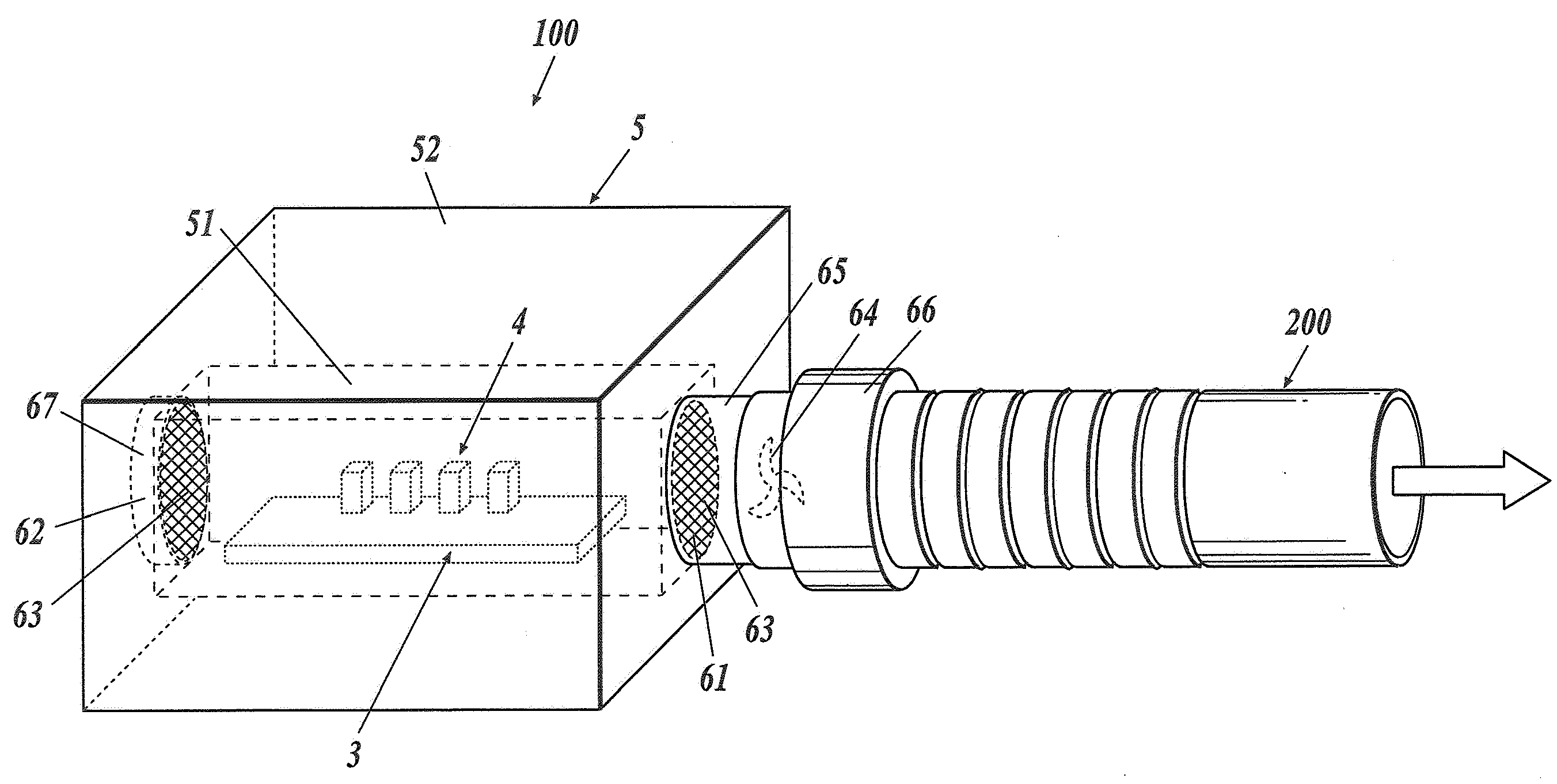
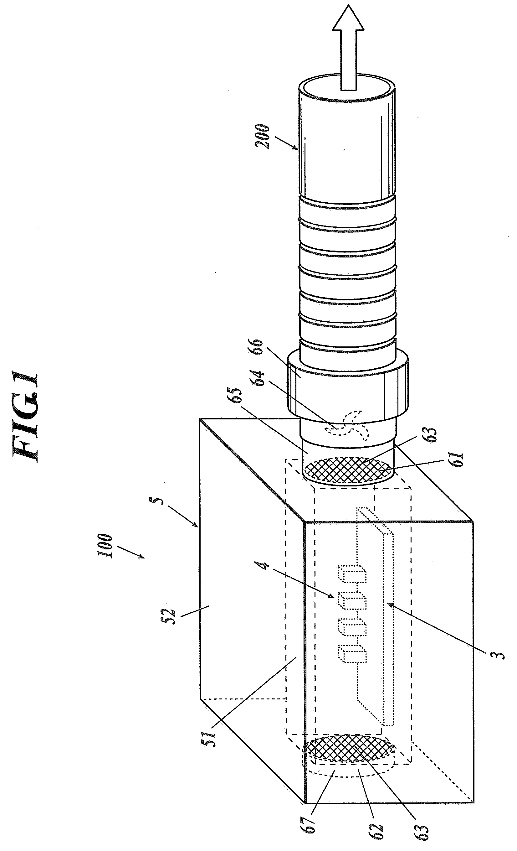
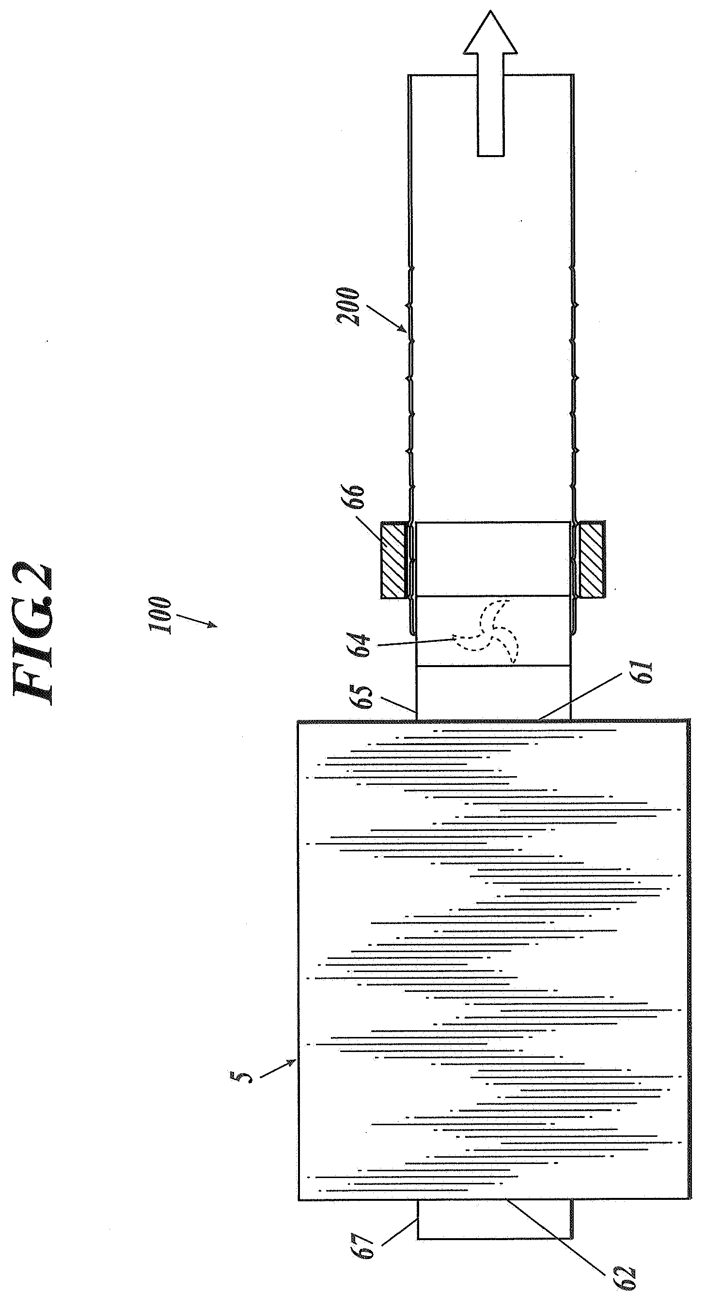
[0025]FIG. 1 is a schematic perspective view showing an inspection apparatus 100, and FIG. 2 is a partially cutaway view showing the inspection apparatus 100 of FIG. 1.

[0026]The inspection apparatus 100 is provided with a housing 5, which is arranged with a cartridge 3 charged with a solution as an inspection sample, and with a liquid feeding device 4 to conduct inspection of the solution by applying external force to the cartridge 3 and by feeding the solution into the cartridge 3.

[0027]The housing 5 is box-shaped, and serves as a safety cabinet which is sealed from the outer atmosphere. At the right side of the housing 5, an outlet 61 is provided to emit discharge air in the housing 5 (processing area 51 described later) to the outside. A discharge duct 65 is connected to the outlet 61, and a sterilization filter 63 is attached to the discharge duct 65. At the left side of the housing 5, an inlet 62 is provided to take outside air into the housing 5 (processing area 51). A suction...

second embodiment

[0051]FIG. 7 is a perspective view of the inspection apparatus 10A, precisely showing a liquid feeding device 4A and the like that are included in a housing 5A; and FIG. 8 is a plan sectional view of FIG. 7. Here, for reasons of drawings, a squeegee 41A, a slider 43A, a guide rail 45A and the like are omitted in FIG. 7.

[0052]In contrast to the inspection apparatus 100 according to the first embodiment, the inspection apparatus 100A according to the second embodiment is provided with cleaning door 54A, in the front of the housing 5A so as to communicate with the processing area 51A. The driving source 7A is provided only in the containing area 52A which is in the back side of the housing 5A. Since other structures are the same as the first embodiment, the same structuring portions are provided with the same numeral with alphabet A, and description thereof is omitted.

[0053]As shown in FIGS. 7 and 8, the cleaning door 54A is provided in a gate fold manner, and is formed so as to penetr...


PUM


Abstract

Disclosed is an inspection apparatus that includes a cartridge including a container which is at least partially structured with an elastic member, the container including inside thereof a plurality of rooms to contain solution and a passage to connect the plurality of rooms; and a housing which is arranged with a liquid feeding device which conducts inspection of the solution by applying external force to the elastic member to move the solution in the passage or in at least one of the rooms, wherein the housing is sealed air-tightly from outside air, and the housing is a safety cabinet to which a sterilization filter is provided at an outlet passage thereby that communicates from inside to external of the housing.

Description

BACKGROUND OF THE INVENTION[0001]1. Field of the Invention[0002]The present invention relates to an inspection apparatus, which is capable of conducting inspection such as mixing, synthesizing, dissolving, separating and the like, automatically in a state where a pathogen which is concerned to be a source of infection and hazardous inspection samples are completely blocked.[0003]2. Description of the Related Art[0004]In recent years, in a case where a pathogen is handled in an inspection room or the like, importance is placed on measures against biohazard to prevent a worker in the inspection room from being infected by the pathogen such as bacteria and virus, and to avoid leakage of the pathogen. The foremost measure with respect to prevention of infection in the inspection room is to provide training of practical skill to handle the pathogen. However, no matter how highly the worker is skilled in handling the pathogen, aerosol infection, splash infection and the like cannot be pre...

Claims


Application Information

Patent Timeline
IPC IPC(8): C12M1/34B01L99/00C12M1/00C12M1/26
CPCB01L1/00B01L1/02B01L2400/0481B01L2200/082B01L2300/0816B01L3/502
Inventor ARARAGI, MUNEKITANAAMI, TAKEO
Owner YOKOGAWA ELECTRIC CORP
Learn More