Digital Electronic Device and Method for Adjusting Signal Level of Digital Signal
a digital signal and electronic device technology, applied in the direction of transducer details, digital/coded amplifier volume compression/expansion, electrical transducers, etc., can solve the disadvantageous increase in size of the apparatus, the disadvantageous complexity of the circuit for adjusting the amount of power (signal level) of the input signal, etc., to achieve the effect of easy adjustmen
- Summary
- Abstract
- Description
- Claims
- Application Information
AI Technical Summary
Benefits of technology
Problems solved by technology
Method used
Image
Examples
first embodiment
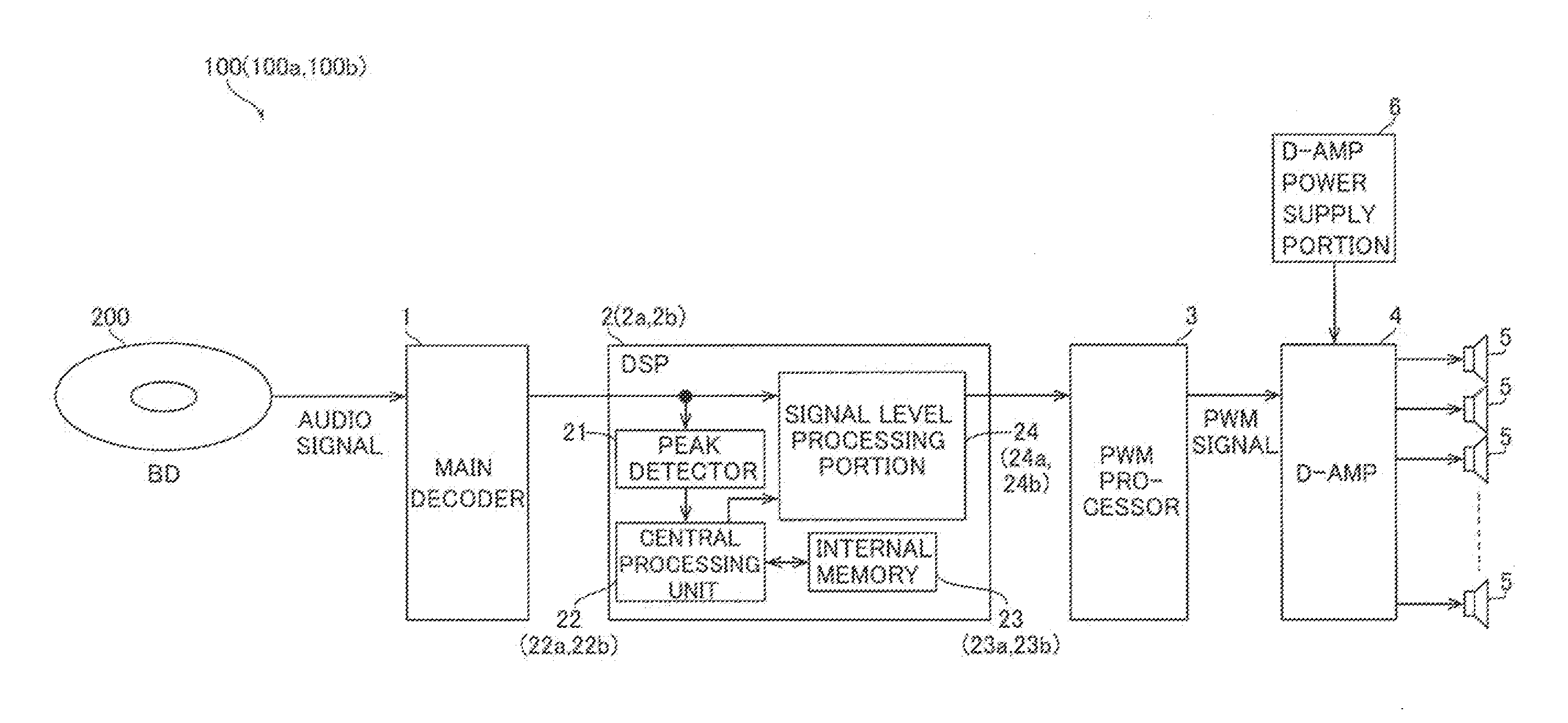
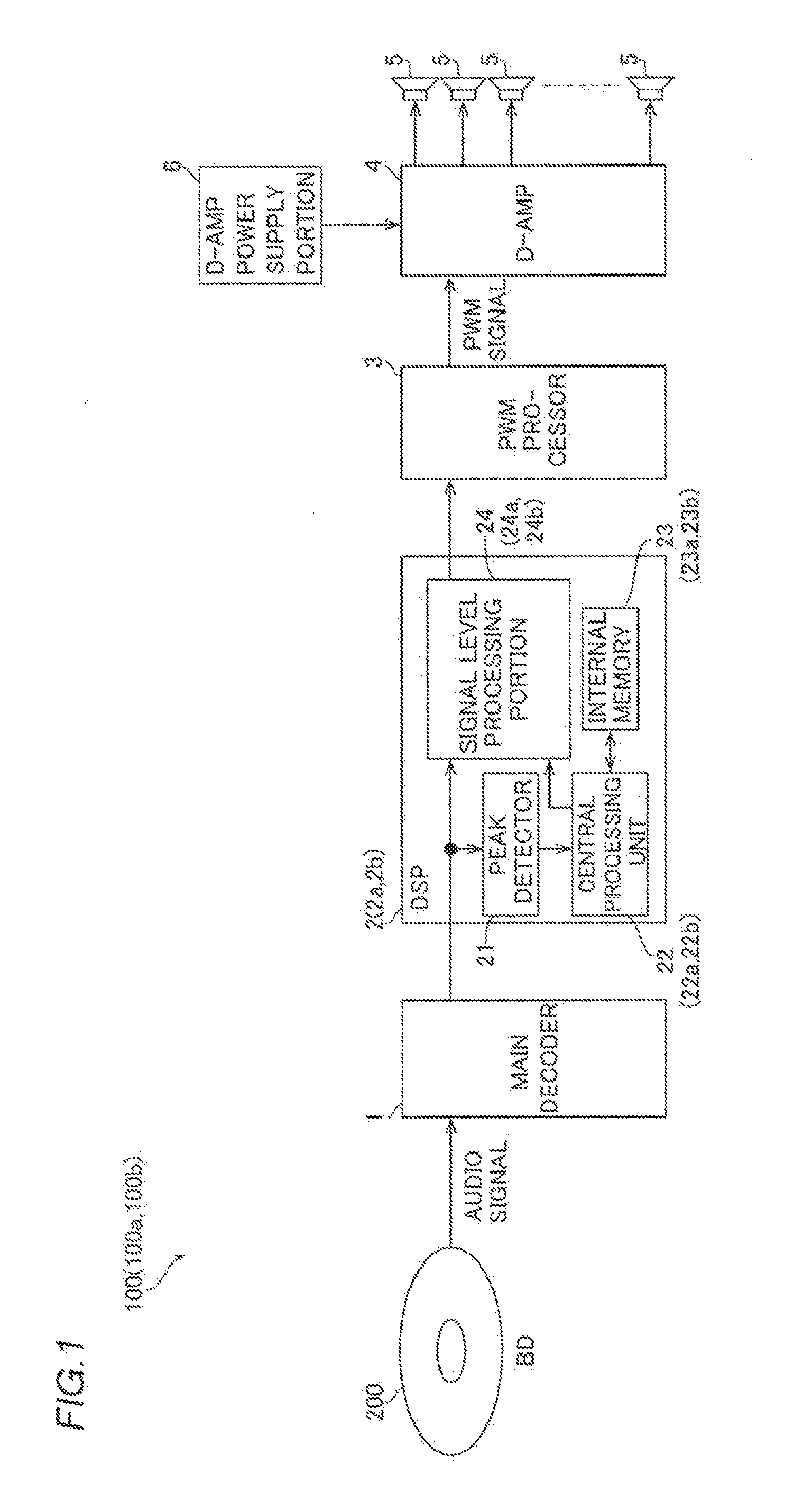
[0040]The structure of an audio system 100 according to a first embodiment of the present invention is now described with reference to FIGS. 1 and 2. This audio system 100 is a digital electronic device configured to be capable of outputting and reproducing audio data (digital data) recorded in a disk-type recording medium such as a BD (Blu-ray Disc) 200.
[0041]As shown in FIG. 1, the audio system 100 includes a decoder 1, a DSP (digital signal processor) 2 connected to the decoder 1, a PWM (pulse width modulation) processor 3 connected to the DSP 2, a D-AMP (digital amplifier) 4 connected to the PWM processor 3, a plurality of speakers 5 connected to the D-AMP 4, and a D-AMP power supply portion 6 connected to the D-AMP 4. The PWM processor 3 is an example of the “PWM conversion portion” in the present invention. The speakers 5 are examples of the “output portion” in the present invention. The D-AMP 4 and the D-AMP power supply portion 6 are examples of the “amplifying portion” and ...
second embodiment
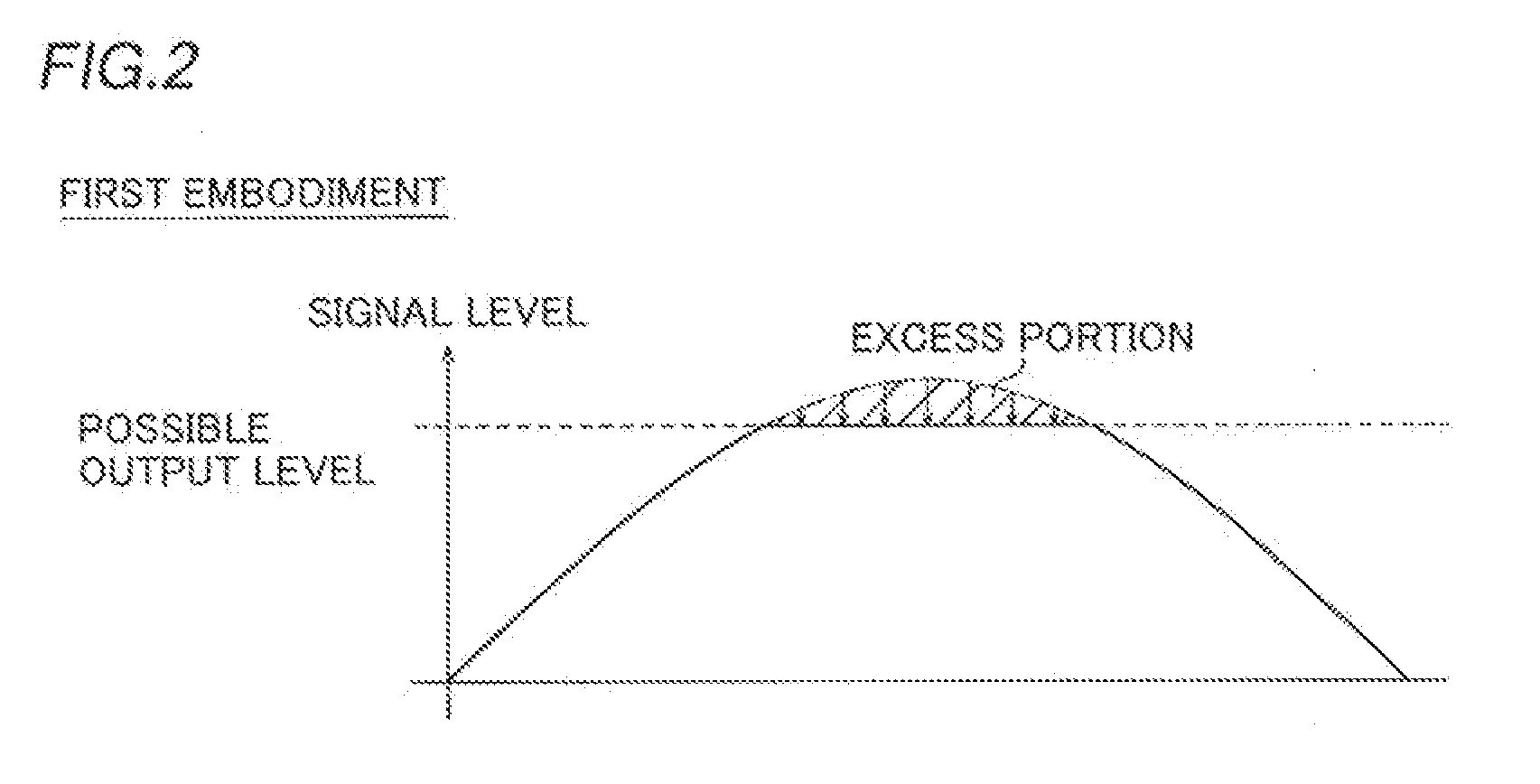
[0068]The structure of an audio system 100a according to a second embodiment of the present invention is now described with reference to FIGS. 1 and 6. In this second embodiment, the entirety of a digital signal is compressed such that the signal level of the entirety of the digital signal becomes not more than a possible output level, unlike the aforementioned first embodiment in which the excess portion (see the shaded area in FIG. 2) of the digital signal whose signal level exceeds the possible output level is compressed such that the signal level of the excess portion becomes equal to the possible output level.
[0069]As shown in FIG. 1, according to the second embodiment, a DSP 2a of the audio system 100a includes a peak detector 21 connected to the output of a decoder 1, a central processing unit 22a connected to the output of the peak detector 21, an internal memory 23a connected to the central processing unit 22a, and a signal level processing portion 24a connected to the outp...
third embodiment
[0078]The structure of an audio system 100b according to a third embodiment of the present invention is now described with reference to FIGS. 1 and 7. In this third embodiment, only an excess portion (see a shaded area in FIG. 7) of an audio signal whose signal level exceeds a possible output level is compressed in a state where the proportion of a signal waveform is maintained such that the signal level of the excess portion becomes not more than the possible output level, unlike the aforementioned second embodiment in which the entirety of the audio signal is compressed such that the signal level of the entirety of the audio signal becomes not more than the possible output level.
[0079]As shown in FIG. 1, according to the third embodiment, a DSP 2b of the audio system 100b includes a peak detector 21 connected to the output of a decoder 1, a central processing unit 22b connected to the output of the peak detector 21, an internal memory 23b connected to the central processing unit 2...
PUM
 Abstract
Description
Claims
Application Information
 - R&D
- Intellectual Property
- Life Sciences
- Materials
- Tech Scout
- Unparalleled Data Quality
- Higher Quality Content
- 60% Fewer Hallucinations
Browse by: Latest US Patents, China's latest patents, Technical Efficacy Thesaurus, Application Domain, Technology Topic, Popular Technical Reports.
© 2025 PatSnap. All rights reserved.Legal|Privacy policy|Modern Slavery Act Transparency Statement|Sitemap|About US| Contact US: help@patsnap.com


