Optical Sources for SPR Applications
a technology of optical sources and applications, applied in the field of optical sources for spr applications, can solve the problems of distorted measurements, unsuitable when high resolution and accuracy are needed, and cannot solve the problem fully
- Summary
- Abstract
- Description
- Claims
- Application Information
AI Technical Summary
Problems solved by technology
Method used
Image

Examples
first embodiment
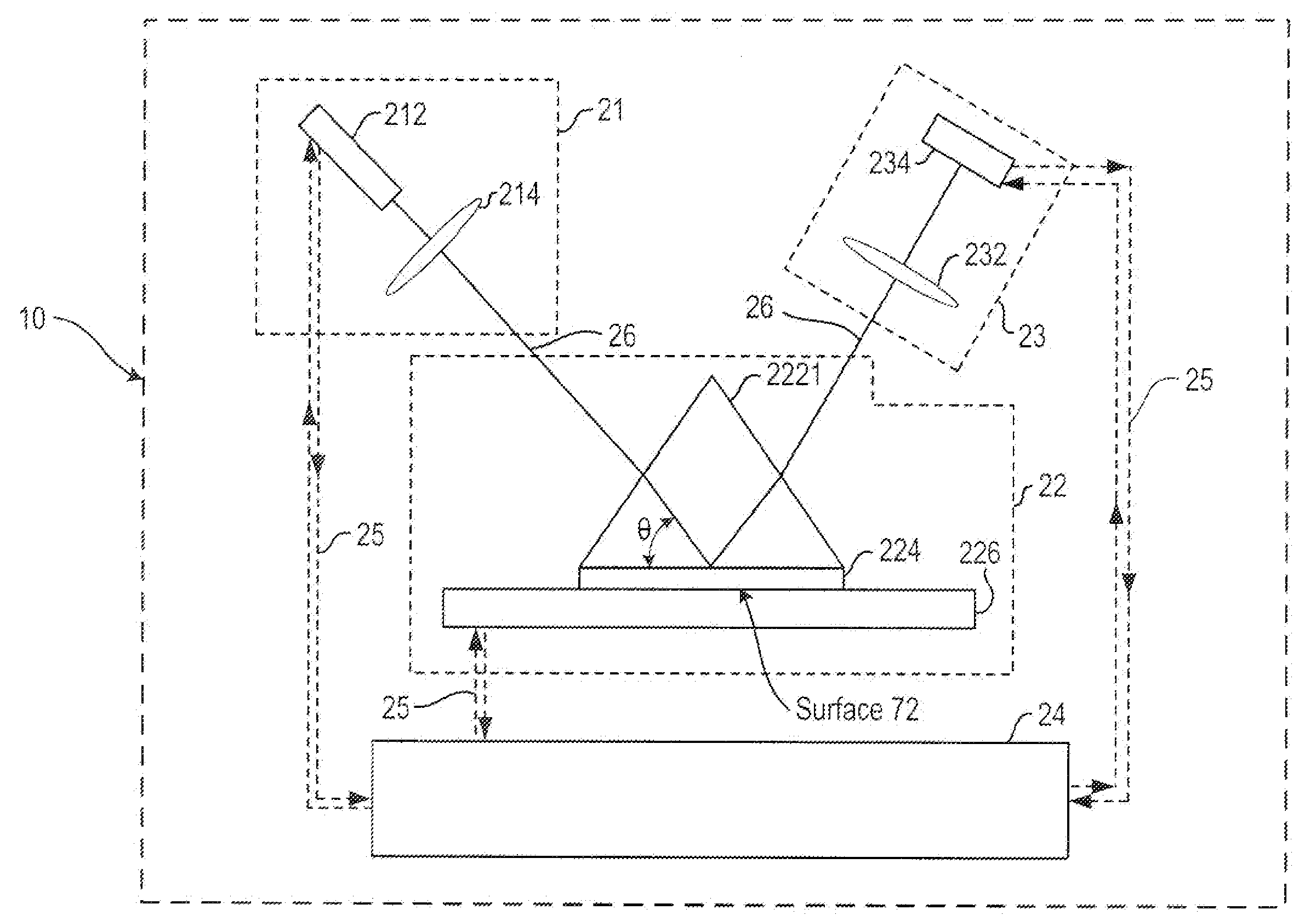
[0026]FIG. 7 shows in detail the various components that make up the SPR system 10. The innovative light source 212 with a high power incoherent output is focused upon a momentum matching optical device 222 through an optional focusing lens 214. A three sided transparent prism 2221, made of glass or plastic, is shown as an embodiment of a momentum matching optical device.
[0027]Metal film 224, e.g. gold, silver or aluminum, is coated to a surface of the prism 2221. FIG. 8 shows immobilized probes 82 chemically bound to the metal film. These immobilized probes, or molecules of matching specificity (to the analytes), trigger the binding of analytes 84 to the metal film.
[0028]The analytes 84, or molecules under test, are exposed to the metal film 224, e.g. through a cavity in the test bed 226 that allows the analytes to bind with immobilized probes 82. The test bed regulates the flow of the analytes, e.g. by a motorized pump (not shown).
[0029]Referring to FIG. 7, the light source 212 is...
second embodiment
[0038]FIG. 11 illustrates in detail this modular diagram described above as the SPR system 10. The processor 24 controls the motor 216, which in turn mechanically alters the angle of incidence of the light source 212. As described earlier, the processor controls the test bed 226, which in turn regulates the flow of the analytes. Similarly, the optical power of the reflected light is measured at the photo detector 234 and the processor records a value for the optical power received corresponding to an angle of incidence at the light source.
[0039]FIG. 12 details the measurement process in a flow chart. Measurements may begin with the reference test bed by sweeping the angle of incident light over the target block to identify a high level of reflectance or brightness (Block 121). The flow within the test bed is regulated to facilitate the movement of analytes and subsequently the adsorption rate of analytes to immobile probes. As the angle of incidence is altered, the surface plasmon r...
third embodiment
[0041]In a SPR system, the processor 24 alters the wavelength of a wavelength-tunable light source and measures the corresponding intensity at the photo detector 234. An intensity minimum will occur when the wavelength of the incident light equals the surface plasmon resonance wavelength. In a manner analogous to the angle shift method described above, changes in the surface plasmon resonance wavelength are monitored and correlated with the binding of molecules to the immobilized probes.
[0042]Amplified Spontaneous Emission (ASE) devices are examples of embodiments of the innovative light source 212. ASEs devices are used to create incoherent radiation at high brightness. ASE is caused by spontaneous emission that becomes amplified through stimulated emissions. Examples of ASE devices are LEDs that are specially designed so that a large portion of the emitted light is produced by the phenomenon of ASE. Other examples are Superluminescent LEDs (SLED), pumped fiber and solid state sour...
PUM
| Property | Measurement | Unit |
|---|---|---|
| width | aaaaa | aaaaa |
| width | aaaaa | aaaaa |
| width | aaaaa | aaaaa |
Abstract
Description
Claims
Application Information
 - R&D
- Intellectual Property
- Life Sciences
- Materials
- Tech Scout
- Unparalleled Data Quality
- Higher Quality Content
- 60% Fewer Hallucinations
Browse by: Latest US Patents, China's latest patents, Technical Efficacy Thesaurus, Application Domain, Technology Topic, Popular Technical Reports.
© 2025 PatSnap. All rights reserved.Legal|Privacy policy|Modern Slavery Act Transparency Statement|Sitemap|About US| Contact US: help@patsnap.com