System for displaying image

Inactive Publication Date: 2008-02-07
INNOLUX CORP
View PDF4 Cites 8 Cited by
  • Summary
  • Abstract
  • Description
  • Claims
  • Application Information

AI Technical Summary

Benefits of technology

[0012]In view of the foregoing, the invention is to provide an image-displaying system with a structure that can reduce the gap between its lighting element and light-guide.
[0014]As mentioned above, in the image-displaying system of the invention, the lighting element is directly pushed by the first elastic element to touch the light-guide. Therefore, the lighting element can be easily aligned with the light-guide so as to enhance the light-emitting efficiency of the backlight module.

Problems solved by technology

Moreover, the light-emitting surface of the LED 13 cannot be guaranteed to be parallel to the light-guide 11.
The light-guide 11 is thus likely to damage the light-emitting surface of the LED 13.

Method used


Image

  • System for displaying image
  • System for displaying image
  • System for displaying image

Examples


Embodiment Construction

[0021]The present invention will be apparent from the following detailed description, which proceeds with reference to the accompanying drawings, wherein the same references relate to the same elements.

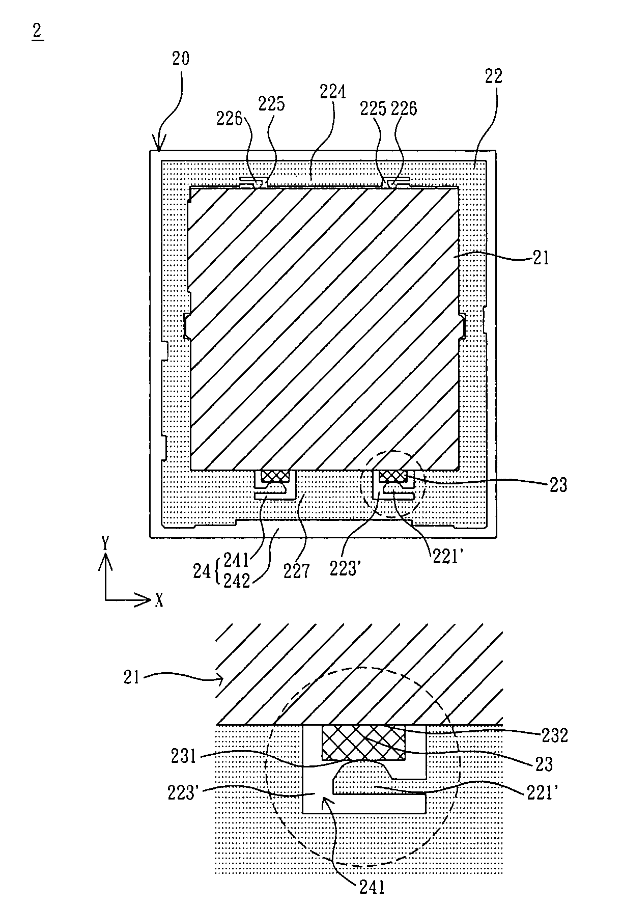
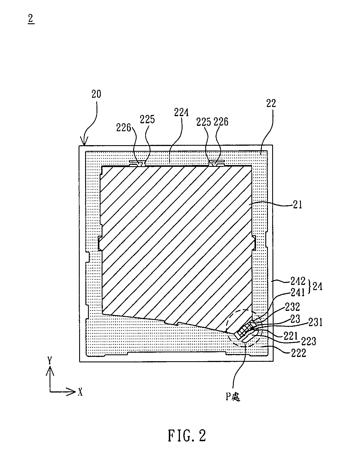
[0022]As shown in FIG. 2, an image-displaying system 2 according to the invention has a backlight module 20 that includes a light-guide 21, a frame body 22, a lighting element 23, and a plastic frame 24. The frame body 22 holds the light-guide 21 and has a first elastic element 221. The lighting element 23 is held in the frame body 22 and has a first side 231 and a second side 232 that are opposite to each other. The first side 231 touches the first elastic element 221 of the frame body 22, and the second side 232 touches the light-guide 21.

[0023]The first side 231 of the lighting element 23 touches against the first elastic element 221 of the frame body 22, so that the first elastic element 221 produces an elastic restoring force. The elastic restoring force pushes the first side 231...


PUM


Abstract

A system for displaying images has a backlight module. The backlight module includes a light-guide, a frame and a lighting element. The frame holds the light-guide and has a first elastic element. The lighting element is held within the frame and has a first side and a second side opposite to each other. The first side touches the first elastic element of the frame. The second side touches the light-guide.

Description

CROSS REFERENCE TO RELATED APPLICATIONS[0001]This Non-provisional application claims priority under 35 U.S.C. §119(a) on Patent Application No(s). 095128404 filed in Taiwan, Republic of China on Aug. 2, 2006, the entire contents of which are hereby incorporated by reference.BACKGROUND OF THE INVENTION[0002]1. Field of Invention[0003]The invention relates to a system for displaying images and, in particular, to an image-displaying system with a backlight module.[0004]2. Related Art[0005]FIG. 1 is a schematic view of a conventional backlight module. As shown in FIG. 1, a small-size backlight module 1, for example, has a frame 12, a light-guide 11, a light-emitting diode (LED) 13, and a plastic frame 14. The plastic frame 14 has a bottom plate 141 and several sidewalls 142. The frame body 12, the light-guide 11, and the LED 13 are disposed on the bottom plate 141 of the plastic frame 14. The frame body 12 is disposed within the sidewalls 142 of the plastic frame 14.[0006]The frame body...

Claims


Application Information

Patent Timeline
IPC IPC(8): G02F1/1335F21V21/00F21V8/00
CPCG02B6/0091
Inventor ZHUANG, PO-CHEINHUANG, LI-CHIAO
Owner INNOLUX CORP
Why Eureka
Try Eureka