Antenna mounting assembly
- Summary
- Abstract
- Description
- Claims
- Application Information
AI Technical Summary
Benefits of technology
Problems solved by technology
Method used
Image
Examples
Embodiment Construction
[0028]An embodiment of the present invention will be described in the following with reference to the accompanying drawings.
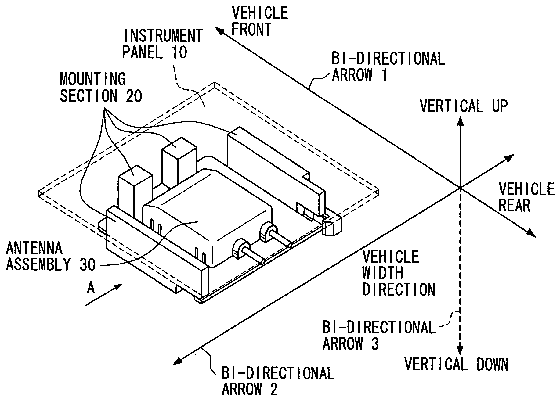
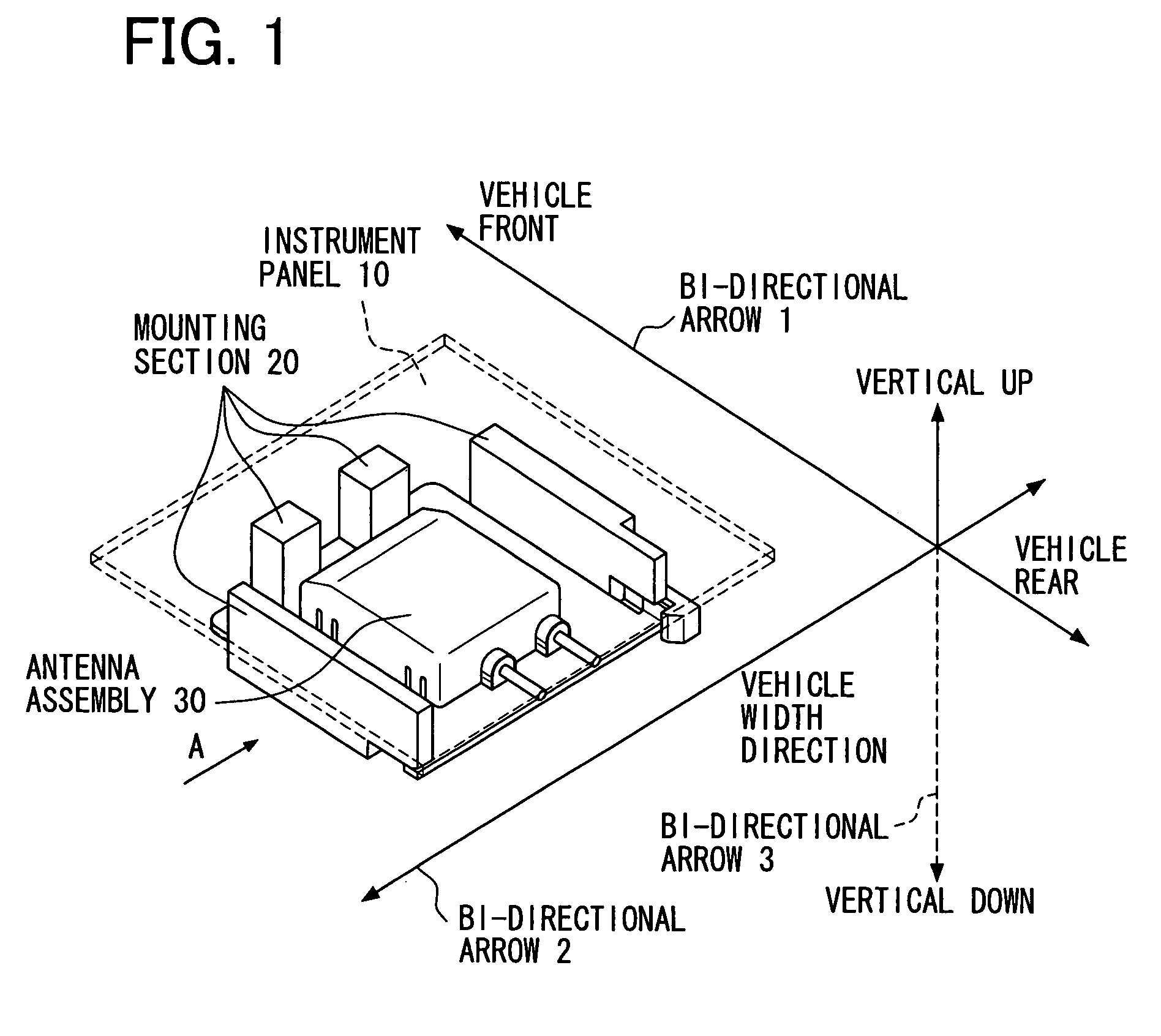
[0029]FIG. 1 is a perspective view showing schematically a state in which an antenna assembly 30 is mounted to an instrument panel-side mounting section 20 and is thereby loaded to an instrument panel 10. (Taking the easiness of seeing the drawing into account, the portion of the instrument panel 10 corresponding to FIG. 10 is cut out in a square shape and is illustrated so that the interior thereof can be seen through). A description will be given below about the configuration of this embodiment.
[0030]A positional relation in the vehicle concerned is the same as that described above in connection with the prior art. That is, the antenna assembly 30 is disposed at a central part in the transverse direction of the vehicle and in a front portion of the vehicle. The relation of the antenna assembly 30 to the vehicle in the longitudinal, transverse and vertical dir...
PUM
 Abstract
Description
Claims
Application Information
 - R&D
- Intellectual Property
- Life Sciences
- Materials
- Tech Scout
- Unparalleled Data Quality
- Higher Quality Content
- 60% Fewer Hallucinations
Browse by: Latest US Patents, China's latest patents, Technical Efficacy Thesaurus, Application Domain, Technology Topic, Popular Technical Reports.
© 2025 PatSnap. All rights reserved.Legal|Privacy policy|Modern Slavery Act Transparency Statement|Sitemap|About US| Contact US: help@patsnap.com


