
Cover for vehicle

Inactive Publication Date: 2008-02-07
TOYOTA JIDOSHA KK
View PDF32 Cites 3 Cited by
  • Summary
  • Abstract
  • Description
  • Claims
  • Application Information

AI Technical Summary

Benefits of technology

[0009]The present invention improves the visibility of the liquid level of a reservoir tank at a liquid level gauge, with the reservoir tank arranged under a cover for a vehicle mounted to an engine compartment so as to cover the reservoir tank from above.

Problems solved by technology

In such a case, the reservoir tank 102 is covered by the cover 103, which darkens the vicinity of the liquid level gauge and thus makes it difficult to check the coolant level through the liquid level gauge.

Method used


Image

  • Cover for vehicle
  • Cover for vehicle
  • Cover for vehicle

Examples


Embodiment Construction

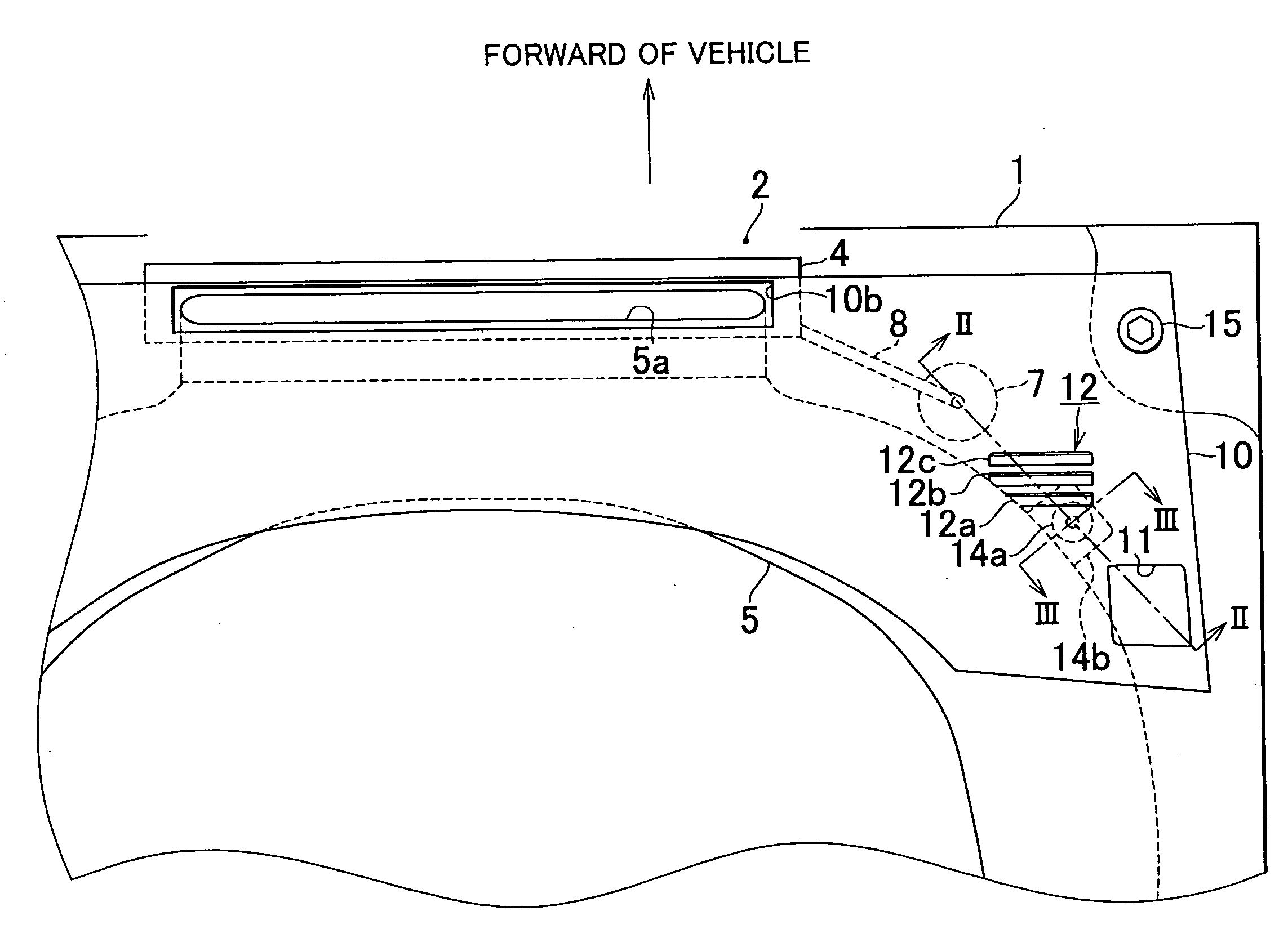
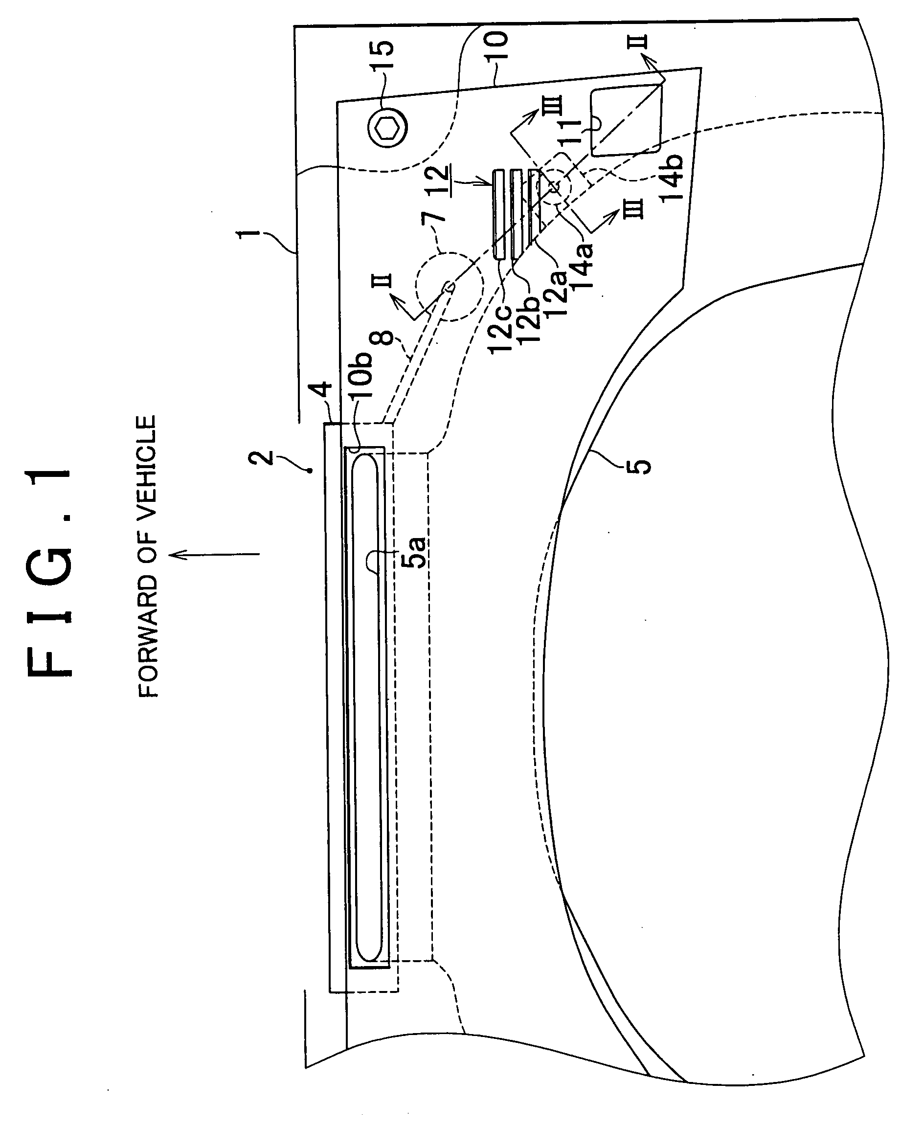
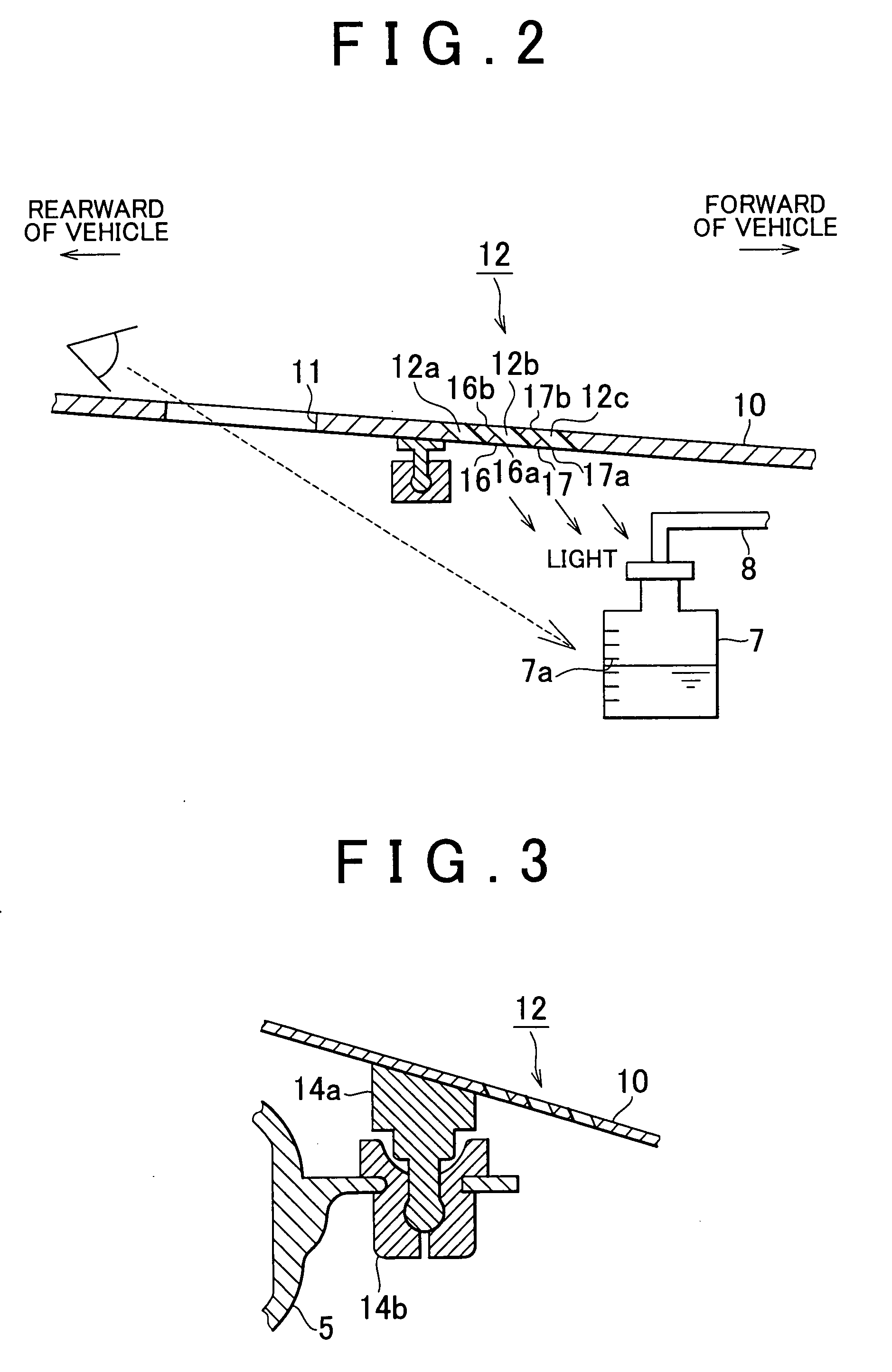
[0037]An embodiment in which a cover for a vehicle according to the present invention is applied as an intake system cover provided in an engine compartment of a V-type engine will now be described with reference to FIGS. 1 to 3. As shown in FIG. 1, a radiator grille 2 is provided at the front of an engine compartment 1 in a vehicle. A radiator 4 is disposed behind the radiator grille 2. An intake duct 5 is provided behind the radiator 4. The intake duct 5 has an air intake opening 5a toward the front of the vehicle, and is divided at its rear part into two branches (not shown) connected to respective banks of the engine. Air is inducted through the radiator grille 2 into the air intake 5a of the intake duct 5, and then supplied through the intake duct 5 to an engine (not shown).

[0038]A reservoir tank 7 is disposed in a space in the engine compartment 1 between a vehicle body and the intake duct 5, and fixed to the vehicle body through a stay (not shown). The reservoir tank 7 is con...


PUM


Abstract

An intake system cover for a vehicle is mounted in an engine compartment to cover a reservoir tank that stores coolant for an engine. The intake system cover for the vehicle is formed with a light introduction opening for introducing light to be directed toward a liquid level gauge at a side of the reservoir tank. The visibility of the liquid level of the reservoir tank at the liquid level gauge is improved.

Description

INCORPORATION BY REFERENCE[0001]The disclosure of Japanese Patent Application No. 2006-213038 filed on Aug. 4, 2006 including the specification, drawings and abstract is incorporated herein by reference in its entirety.BACKGROUND OF THE INVENTION[0002]1. Field of the Invention[0003]The present invention relates to a cover for a vehicle.[0004]2. Description of the Related Art[0005]An engine for a vehicle is provided with a cooling system that maintains the engine at an appropriate temperature according to the operating condition. The cooling system includes a radiator that releases the heat of coolant in the engine to the outside, and a reservoir tank that stores coolant for a refill. In the cooling system, coolant is supplied from the reservoir tank to the radiator, and discharged in the opposite way, according to pressure changes of coolant in the radiator.[0006]The reservoir tank is disposed, for example, at the rear of the radiator 101 in the engine compartment 100, as shown in F...

Claims


Application Information

Patent Timeline
IPC IPC(8): B62D25/00B62D39/00
CPCF01P11/18B62D25/12
Inventor OBA, TORUSUZUKI, AKIRA
Owner TOYOTA JIDOSHA KK
Learn More