Frequency measurement system for low modulation index digital fm/pm communication

a technology of low modulation index and frequency measurement system, applied in the direction of modulated carrier system, transmission, angle demodulation, etc., can solve the problem of difficult continuous phase locking of a frequency modulated (fm) signal, the frequency measurement method is not suitable for high data rate fm communication system, and the relative long time for counting and determining the frequency of high frequency measurement using counters

Active Publication Date: 2008-01-31
AL EIDAN ABDULLAH A
View PDF2 Cites 20 Cited by
  • Summary
  • Abstract
  • Description
  • Claims
  • Application Information

AI Technical Summary

Problems solved by technology

However, this frequency measurement method is not suitable for high data rate FM communication system as it requires transmitting many cycles per bit.
Second, continuous phase locking of a frequency modulated (FM) signal may be difficult, at least when the frequency deviation of the input signal is wide.
High frequency measurement using counters takes a relative long time for counting and determining the frequency, which has the effect of reducing the data rate.
Also this heterodyne technique limits the data rate with the resulting low (Beat) frequency signal, as a relatively long time is needed to measure one cycle of this frequency.
Accordingly, this method is not well suited for high data rate FM communication systems.
U.S. Pat. No. 6,630,820 describes a method and apparatus for measuring instantaneous frequency of FM modulated signal, however this technique of digitizing the FM signal and computing the instantaneous frequency is not fast enough for high speed digital FSK-NBFM applications.
Although U.S. Pat. No. 5,757,858 discloses a dual mode digital communication system based upon a frequency modulated (FM) mode and a code division multiple-access (CDMA) mode, it fails to disclose a digital FSK method.
Similarly, although U.S. Pat. No. 6,484,112 describes a method for estimating the frequency of a time signal by means of a discrete Fourier transformation and interpolation, it fails to analyze multi-sample messages at high speed in order to determine the peak of spectral power density.

Method used


Image

  • Frequency measurement system for low modulation index digital fm/pm communication
  • Frequency measurement system for low modulation index digital fm/pm communication
  • Frequency measurement system for low modulation index digital fm/pm communication

Examples


Embodiment Construction

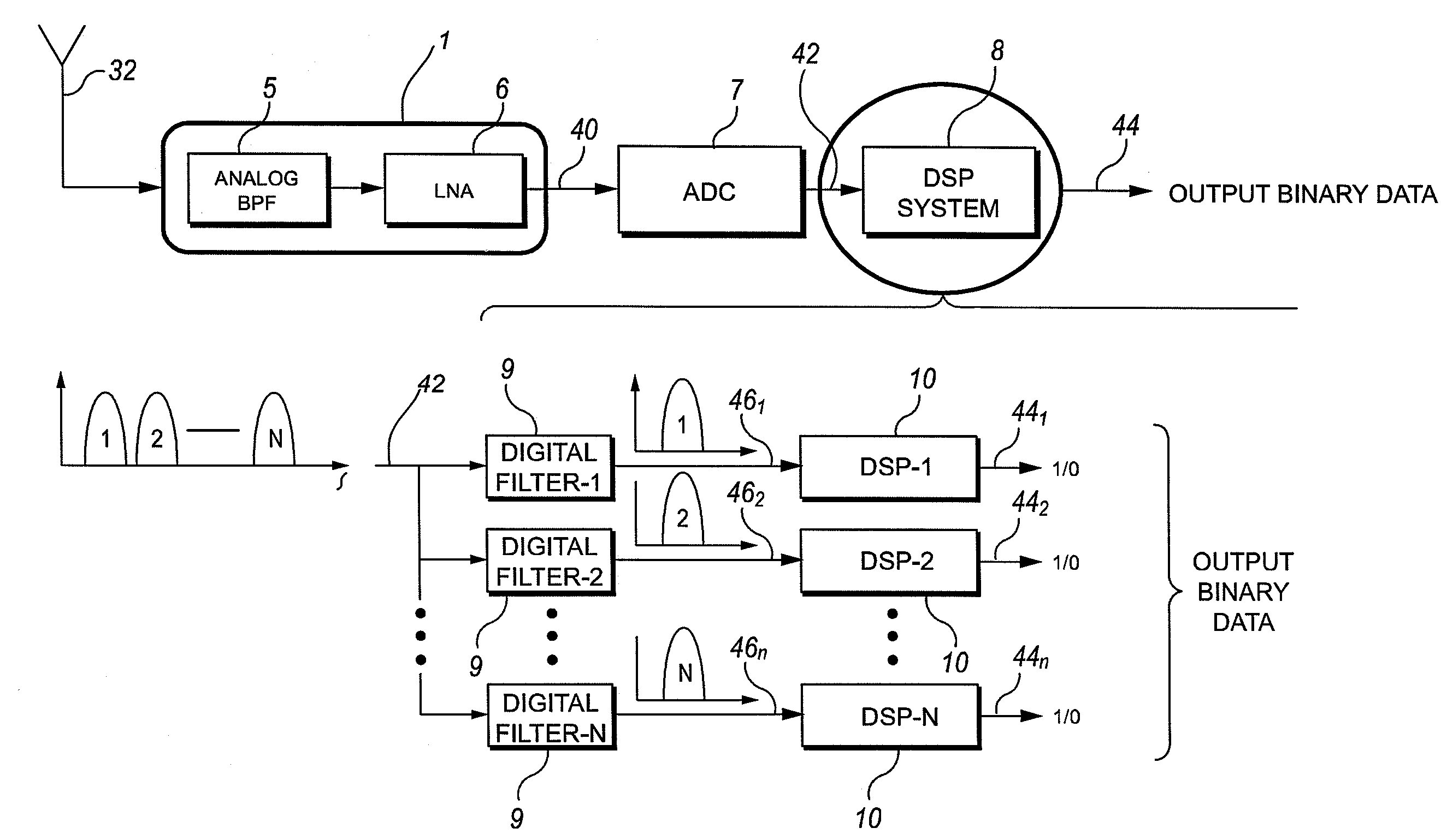
[0046]In frequency modulation / phase modulation FM / PM, there are two stages of frequency deviation. The first stage, where primary frequency deviation is performed, occurs in the frequency / phase modulator. In the modulator, the carrier frequency fluctuates or deviates at a rate according to the amplitude or to the amplitude and frequency of the modulating signal. The second stage, where secondary frequency deviation is performed, occurs in the frequency multiplier stage. The result of the two stages of frequency deviation offers a means for obtaining practically any desired amount or value for the carrier frequency, frequency deviation and modulation index.

[0047]A modulation index is a quantity that indicates by how much the modulated variable varies around its unmodulated level. For FM, the modulation index relates to the variations in the frequency of the carrier signal and is equal to:

h=Δffm

[0048]In an FM / PM receiver, the value of the modulation index h determines the accuracy of ...


PUM


Abstract

Apparatus and methods for data demodulation in FM-FSK communication systems may include comparing the power spectral density (PSD) of the received frequency spectrum with that of the previously received samples using digital signal processing on a multi-sample message. A narrow band FM-FSK receiver may include a filter configured to pass FM signal components of a predetermined signal band, a memory configured to store the filtered signal component, and a DSP operably connected to the filter and the memory. The DSP may be configured to output a digital signal based upon a comparison of successive DSP calculated frequencies associated with a peak power of a power spectrum density (PSD) of successive samples of the filtered multi-sample message.

Description

CROSS REFERENCE TO RELATED APPLICATIONS[0001]This invention is related to U.S. Pat. No. 7,027,505 entitled “System and Method for Bandwidth Compression of Frequency and Phase Modulation Signals and Suppression of the Upper and Lower Sidebands From the Transmission Medium,” to A. Al-Eidan, and hereby incorporated by reference in its entirety.BACKGROUND[0002]The disclosed embodiments relate to frequency measurements and the detection of digital data using digital signal processors (DSP) in frequency shift keying (FSK) based communication systems. Specifically, the invention relates to a communications system and method for transmitting and receiving digital data using FSK and frequency modulation (FM) techniques on narrowband or very narrowband channels.[0003]Most basic communication systems use frequency references. A frequency reference is a stable signal (source) with a constant frequency. It can be a ceramic resonator or a quartz crystal oscillator. The ceramic resonator is often ...

Claims


Application Information

Patent Timeline
Patent Type & Authority Applications(United States)
IPC IPC(8): H04L27/14
CPCH04L27/14H04L27/12
Inventor AL-EIDAN, ABDULLAH A.
Owner AL EIDAN ABDULLAH A
Why Eureka
Try Eureka