
HGA having separate dimple element, disk drive unit with the same, and manufacturing method thereof

a manufacturing method and dimple element technology, applied in the direction of data recording, magnetic recording, instruments, etc., can solve the problems of deteriorating the reading/writing capability of the disk drive unit when in use, affecting the flying attitude and affecting the flying performance of the slider. , to achieve the effect of improving the flying performance of the slider, simplifying the manufacturing process, and improving the manufacturing accuracy of the slider

Inactive Publication Date: 2008-01-31
SAE MAGNETICS (HK) LTD
View PDF13 Cites 29 Cited by
  • Summary
  • Abstract
  • Description
  • Claims
  • Application Information

AI Technical Summary

Benefits of technology

The present invention provides a HGA for a disk drive unit that can improve flying performance of a slider, simplify manufacturing process and improve manufacturing accuracy. The HGA comprises a slider, a load beam, a flexure to support the slider and connect with the load beam, and a separate dimple element having a dimple. The dimple extends through the locating hole and supports the flexure at a position corresponding to a center area of the slider. The separate dimple element may further comprise a base portion to hold the dimple, which is fixed to the load beam by any suitable manner such as laser welding or adhesive. The disk drive unit comprises a HGA, a drive arm connected to the HGA, a disk and a spindle motor to spin the disk. The method for manufacturing a HGA comprises the steps of providing a flexure and a load beam with a locating hole formed therein, assembling the flexure and the load beam together, providing a slider and mounting it to the flexure, providing a separate dimple element having a dimple, and assembling the separate dimple element to the load beam to make the dimple extend through the locating hole and support the flexure at a position corresponding to a center area of the slider.

Problems solved by technology

However, in conventional HGA described above, since the dimple is integrally formed with the load beam, due to reasons such as die fabrication and dimension limitation of machine, it is difficult to manufacture a load beam with a size-reduced dimple incorporated thereon; consequently, when a slider of smaller form factor is mounted on the flexure, the dimple appears larger and larger with respect to the slider, and the contact area between the original dimple and size-reduced slider will be changed.
This change in turn degrades flying attitude of the slider and finally influences badly the flying performance of the slider over the rotary disk, thereby deteriorating reading / writing capability of the disk drive unit when in use.
Consequently, when the slider is mounted on the flexure, the slider will have poor alignment with the dimple, thus further negatively affecting flying attitude and performance of the slider.
Moreover, the tilt of the flexure relative to the load beam results in difficult in slider electrical bonding.

Method used


Image

  • HGA having separate dimple element, disk drive unit with the same, and manufacturing method thereof
  • HGA having separate dimple element, disk drive unit with the same, and manufacturing method thereof
  • HGA having separate dimple element, disk drive unit with the same, and manufacturing method thereof

Examples


Embodiment Construction

[0033]Several example embodiments of a HGA will now be described. It is noted that the HGA may be implemented in any suitable disk drive device having a HGA, regardless of the specific structure of the HGA as illustrated in the figures. That is, the invention may be used in any suitable device having a HGA in any industry.

[0034]FIGS. 3a-3f show a HGA according to an embodiment of the invention. As illustrated, the HGA 200 comprises a load beam 260, a flexure 208 to connect with the load beam 260, a slider 203 held on the flexure 208 and a separate dimple element 210 mounted on the load beam 260. As shown in FIG. 3a, the whole HGA 200 is mounted to a motor arm 204, which in turn drives the whole HGA 200 and the slider 203 mounted thereon to rotate above a disk, thus realizing reading / writing operation of the slider 203.

[0035]The flexure 208 is preferably made of resilient material to resiliently support the slider 203 thereon. A plurality of traces (not shown) may be additionally or ...


PUM

PropertyMeasurementUnit
areaaaaaaaaaaa
lift forceaaaaaaaaaa
spring forcesaaaaaaaaaa

Abstract

A HGA of the invention includes a slider, a load beam having a locating hole formed therein; a flexure to support the slider and connect with the load beam; a separate dimple element having a dimple to extend through the locating hole and support the flexure at a position corresponding to a center area of the slider. The invention also discloses a method for manufacturing the HGA and a disk drive unit with the HGA.

Description

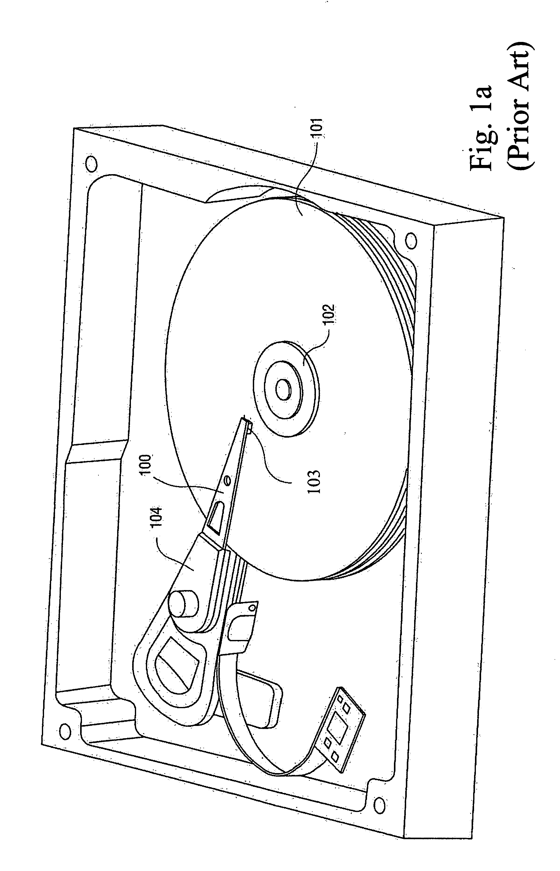
FIELD OF THE INVENTION[0001]The present invention relates to information recording disk drive devices and, more particularly, to a head gimbal assembly (HGA) having a separate dimple element, disk drive unit with the same, and manufacturing method thereof.BACKGROUND OF THE INVENTION[0002]One known type of information storage device is a disk drive device that uses magnetic media to store data and a movable read / write head that is positioned over the media to selectively read from or write to the disk.[0003]FIGS. 1a and 1b illustrate a conventional disk drive device and show a magnetic disk 101 mounted on a spindle motor 102 for spinning the disk 101. A voice coil motor arm 104 carries a head gimbal assembly (HGA) 100 that includes a slider 103 incorporating a read / write head. A voice-coil motor (VCM, not labeled) is provided for controlling the motion of the motor arm 104 and, in turn, controlling the slider 103 to move from track to track across the surface of the disk 101, thereby...

Claims


Application Information

Patent Timeline
Patent Type & Authority Applications(United States)
IPC IPC(8): G11B5/48
CPCG11B5/4826
Inventor YANG, HUAI
Owner SAE MAGNETICS (HK) LTD
Learn More