Digital Sensor Whole Image Scanning Device

a scanning device and digital sensor technology, applied in the field of scanning devices, can solve the problems of limiting the scanning speed to the physical movement, adding to the expense and complication of the device, and the previous scanner versions fall into several problem areas, so as to achieve the effect of quickly and efficiently creating images of objects

Inactive Publication Date: 2008-01-31
SUNDNES JOHN PHILLIP
View PDF0 Cites 20 Cited by
  • Summary
  • Abstract
  • Description
  • Claims
  • Application Information

AI Technical Summary

Benefits of technology

[0027] (11) Scanners could use multiple digital camera sensor assemblies, to allow scanning speeds to double or more depending on the number of assemblies and the sequence of scanning.
[0028] In accordance with the present invention I propose a new scanning device to rapidly and efficiently create images of objects, by combining existing digital camera technology in a new and novel way. I propose a casing, similar to existing scanning device casings (a plastic box), with a sheet of translucent material to hold the scanned object. Within the casing is a digital camera photo sensor (i.e. Foveon sensors, Color filter array sensors, Active Pixel sensors, etc.), with a light source and a shutter such that a light source and an open shutter can create an image on the sensor in an instant. The sensor, shutter, and related optics would be focused to the image size on the translucent plate (object holder), and could have an adjustable lens to scan large or small objects on the translucent plate. Also within the casing is a power source (battery or plug in), a means of digital storage (RAM or ROM), and a means to convey the digital files created to another device (i.e. a USB® connection with a computer, fax, printer, etc.).
[0029] Another improvement of the invention (not required but recommended for added function) is to wire a typical electronic camera viewfinder (like Liquid Crystal Displays currently found on digital cameras) on the exterior surface of the scanner. This shows the actua

Problems solved by technology

Previous versions of scanners fall into several problem areas.
First, are scanners or facsimiles that utilize a cumbersome Charge Coupled Device (CCD) sensor.
This movement limits the scanning speed to the physical movement, and requires motors, gears, stabilizers, etc. which add to the expense and complication of the device.
The required movement requires significant amounts of energy and time to complete, not to mention the expensive motors, gears, and stabilizers.
Also, the information from the sensor is fed to the a computer a line at a time, which means that movement of the scanned object during scanning ruins the scan, and that the resulting computer file of the scan cannot be completed until the physical movement of the scan is completed.
This makes the scanning event extremely slow.
This places limitations on speed of file creation, and the limitations of holding the scanned object still during the scanning process similar to the CCD scanning device.
This process is usually faster than the CCD or CIS scanner process, but does not allow for digital files to be created of the original documents.
All of these scanners in the referenced patents suffer from essentially the same limitations.
First, this greatly limits the speed at which scans can be completed.
Second, it requires elongated light bars and scanning elements, which can be expensive and complicated.
Third, the movement requires gears, motors, and stabilizers, which furthers the expense and complication of manufacturing, and requires substantial energy to complete.
None of these scanners can capture an image in the fraction of an instant the way a digital camera sensor can, with a single burst of light from a potentially small light source.
None of these scanners can provide a viewfinder on the exterior of the scanner to depict the same image the sensor lens is viewing (under a cover), to aid in alignment of the scanned object prior to scanning, and to “proof” the image following the scan.

Method used


Image

  • Digital Sensor Whole Image Scanning Device
  • Digital Sensor Whole Image Scanning Device
  • Digital Sensor Whole Image Scanning Device

Examples


Embodiment Construction

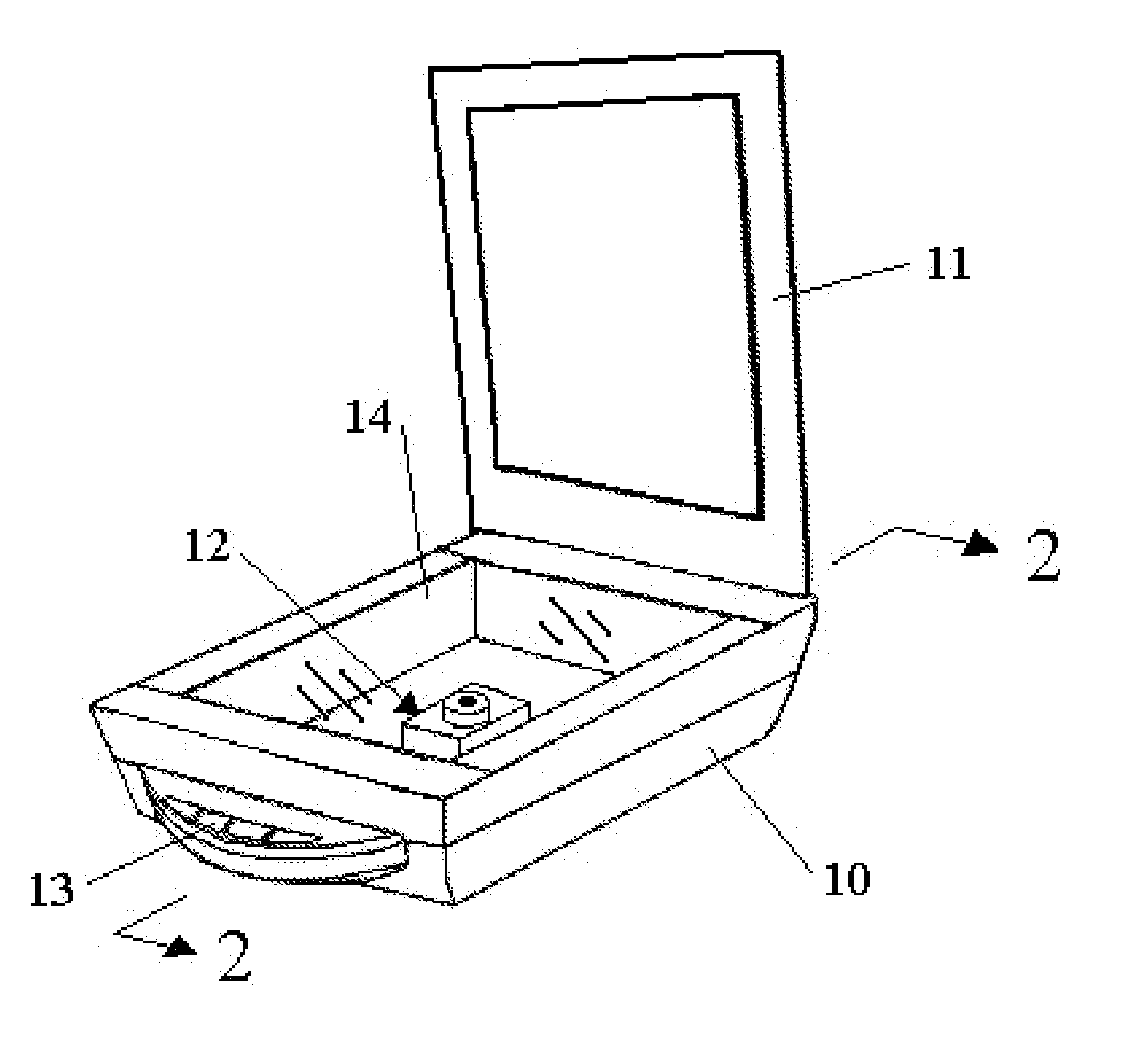
[0076]FIG. 1 depicts the scanning device assembly with the exterior casing 10, integral internal digital camera sensor apparatus 12 inside, replacing the sensor bar, light bar, and all motorized elements. Also depicted is the translucent plate 14 for holding scanned objects in relative position to the digital sensor, external controls 13 for operating the unit, and the optional lid / cover 11 for the device.

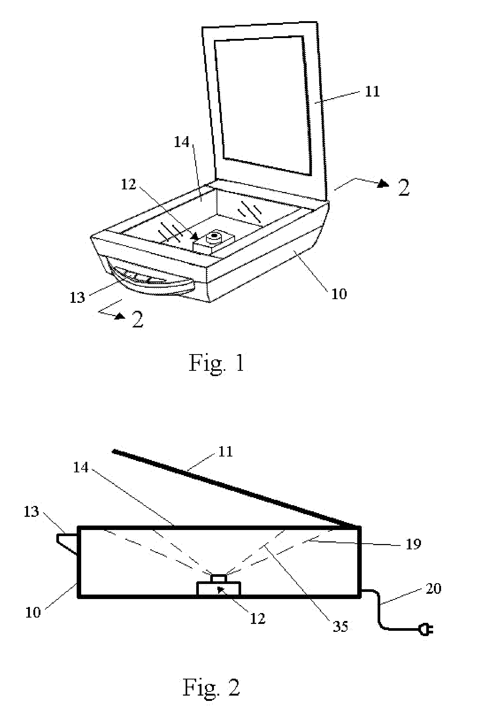
[0077]FIG. 2 depicts a cutaway section of the assembly. This figure shows the casing 10 in section, the lid 11, a power source 20 (note this could be plug in or internal battery source), the digital photo / image apparatus 12, and the relation of the image focal area 19 to the translucent plane 14. This figure also depicts the changed focal area 35 on the translucent plane by changing the focus of the camera lens.

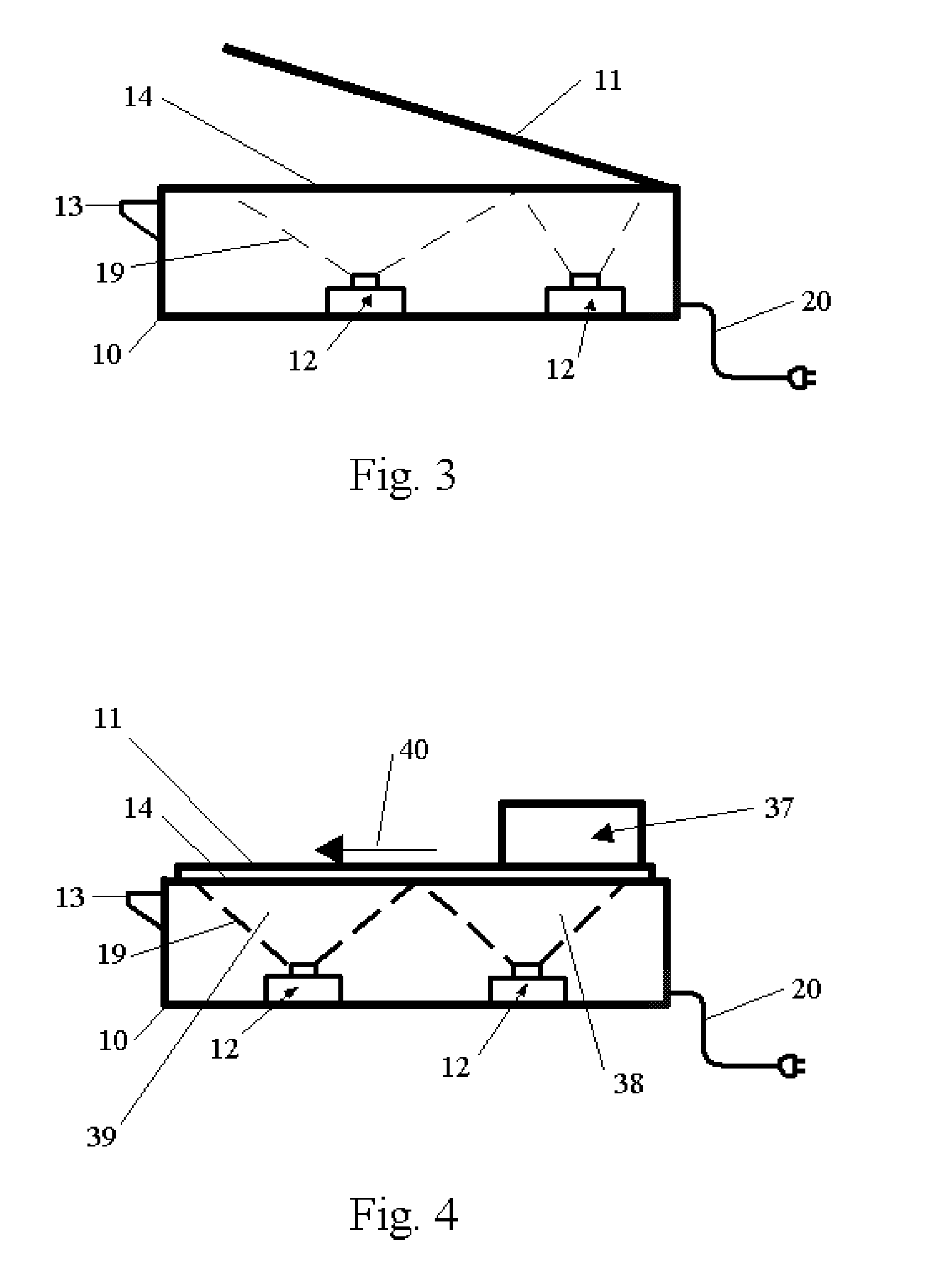
FIGS. 3 and 4 Additional Embodiments

[0078]FIG. 3 depicts a cross section of an additional embodiment scanner with similar elements to that depicted in FIG. 2, showing the...


PUM


Abstract

A digital scanning device 22 (FIGS. 1-7) whereby a digital camera infrastructure 12 is utilized as the primary element to “scan” objects. The scanned object 21 is placed on a translucent plate 14 and the controls 13 are activated initiating the scan. It is possible to arrange the controls, such that pressure on the scanning device 22 affirms the object to be scanned 21 is on the device and initiates the scan function in a fluid motion. The camera assembly 12 captures the scanned image 23 and either a) sends it to digital storage assembly 24, b) sends it to a computer assembly 25, c) sends it to a printer assembly 26, d) sends it to a fax machine assembly 30, e) sends it to a viewing device assembly 36.

Description

RELATED APPLICATIONS [0001] This application claims the benefit of provisional patent application No. 60 / 834335 filed Jul. 31, 2006 by the present inventor.CROSS REFERENCES TO RELATED APPLICATIONS [0002] None. FEDERALLY SPONSORED RESEARCH [0003] None. SEQUENCE LISTING [0004] None. FIELD OF INVENTION [0005] This invention pertains to scanning devices, such as currently available computer scanners, facsimile scanners, photocopier scanners, etc. Virtually all currently available “scanners” rely on physical movement of the scanned object past a scanning element (generally an elongated digital sensor and an elongated light source). This physical movement requires motors, gears, paper handlers, etc. and imposes scanning speed limits based on the physics of the mechanical movement required. All the added hardware to create the movement requires added expense and complication of the scanner. [0006] My proposed invention is essentially fixing a digital camera element in a “scanner” casing, t...

Claims


Application Information

Patent Timeline
IPC IPC(8): H04N1/04
CPCH04N1/00249H04N1/10H04N2201/0416H04N2101/00H04N1/195
Inventor SUNDNES, JOHN PHILLIP
Owner SUNDNES JOHN PHILLIP
Why Eureka
Try Eureka