
Reeling Method and System as Well as an Measuring Apparatus

Active Publication Date: 2008-01-24
VALMET TECHNOLOGIES INC
View PDF7 Cites 18 Cited by
  • Summary
  • Abstract
  • Description
  • Claims
  • Application Information

AI Technical Summary

Benefits of technology

[0033] According to an example, the cutting is made from the section of the migration exchange of a reel or from the bottom of the reel. According to another example, a web track is profiled on the calender by watering the web in the MD-direction at thick sections thereof. According to another third example, the tape strip / a paper strip is fed with a suitable feeding device in the MD-direction with the web to the reel, where the CD-profile of the reel is straightened by means of the said tape / paper strip. According to another fourth example, the desired bombering or pattern, which corrects the CD-profile, is made for example in the tampur stock on a tampur roll with a help of a MD-directional tape / paper strip. Then it can be advantageous that the tape fastening or the adaptation of the strip is made, advantageously, automatically, whereby a better CD-profile is obtained to the following machine reel according to CD-directional hardness profile that has been measured towards the end of the previous machine reel. According to another fifth example, the material web is covered at the sections of faults of the CD-profile that have been locally perceived in the MD-direction.
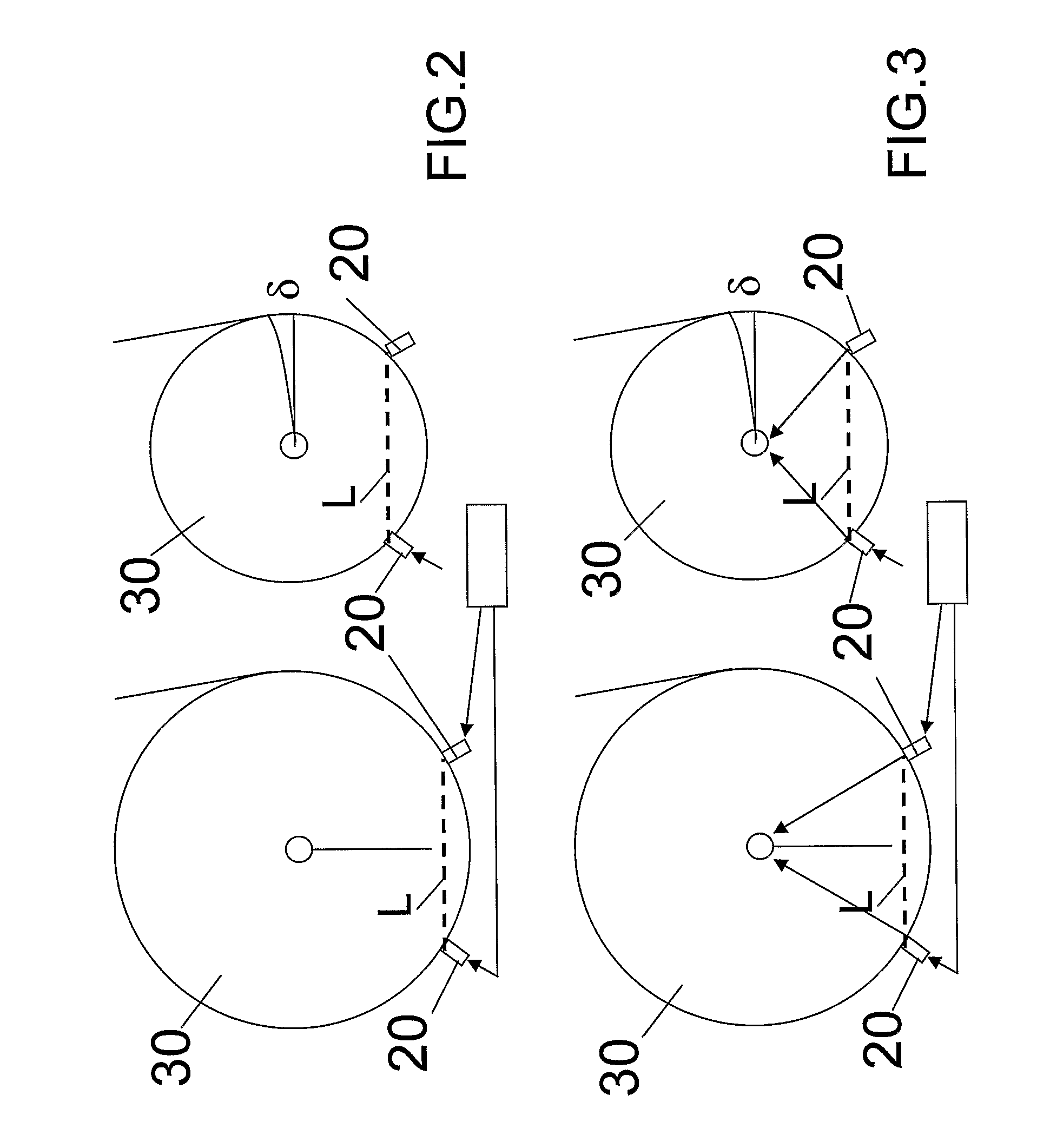
[0038] One can state about the advantages of the measuring device according to the invention, in the measuring of the generally linear hardness profile, that the motion course can be cost-effectively carried out as such with known components and that the space requirement of the measuring device is smaller than essentially known and that the linear load functions without problems and without danger for the materialising of measuring errors without the long and lever-like load stem, whereby an attempt has been made to minimize measuring errors earlier, the space requirement needed by the measuring arrangements which makes more reasonable investment possibilities possible.

Problems solved by technology

Furthermore, the length and stretchability of the web affect the stability of the strains of the reel in addition to thickness and the compressibility.
It will form into a problem in material web machines to be equipped with in-line cutting stations, production disturbances that are caused by the quality of the machine reel on cutting stations, operation of which is automated and occupation of which is minor.
With the present methods quality of the reel; that is, reel-up faults, a handling of the machine reel, an intermediate storing fault; one cannot control carefully enough when the reel is transferred to the unwinding of the cutting station, in-line.
Furthermore, the defects in quality of the machine reel cause track breaks and wreck on the cutting station and on the other hand, because of on the other hand, the decrease of the operating personnel are not labour to the dismantling of a break reject, which is created with the cutting station and of break situations any more.
The biggest problem from an uneven parallel with the shaft of the reel CD-cross section profile is a consequence from the air which gets to the reel and can cause the slide of the reel between the layers and even the falling of the reel.
When the CD-profile is uneven, the forming ridges will prevent out in the direction of the radius of the reel to the thicker sections of the reel in the entrance of the air which has got in the reel, whereby the air, which reduces the friction and makes the forming of the even and of the good quality reel more difficult essentially stays.
In that case, however, this will lead into the problem that at the same time trim-dissipation are caused to both ends of the reel, in other words an oscillating movement of the reel has to be cut at both heads thereof.
However, the weakness of this follow-up device is that the follow-up device is not suitable for reel-ups, where the diameter of the reel will increase remarkably, because the measuring geometry of the follow-up device changes and causes the mistake, which causes considerable investment problems and because the follow-up device requires considerably much space.

Method used


Image

  • Reeling Method and System as Well as an Measuring Apparatus
  • Reeling Method and System as Well as an Measuring Apparatus
  • Reeling Method and System as Well as an Measuring Apparatus

Examples


Embodiment Construction

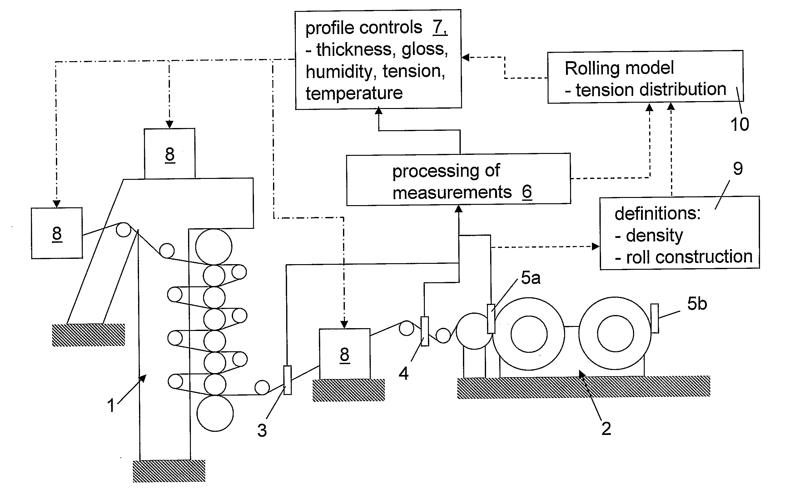
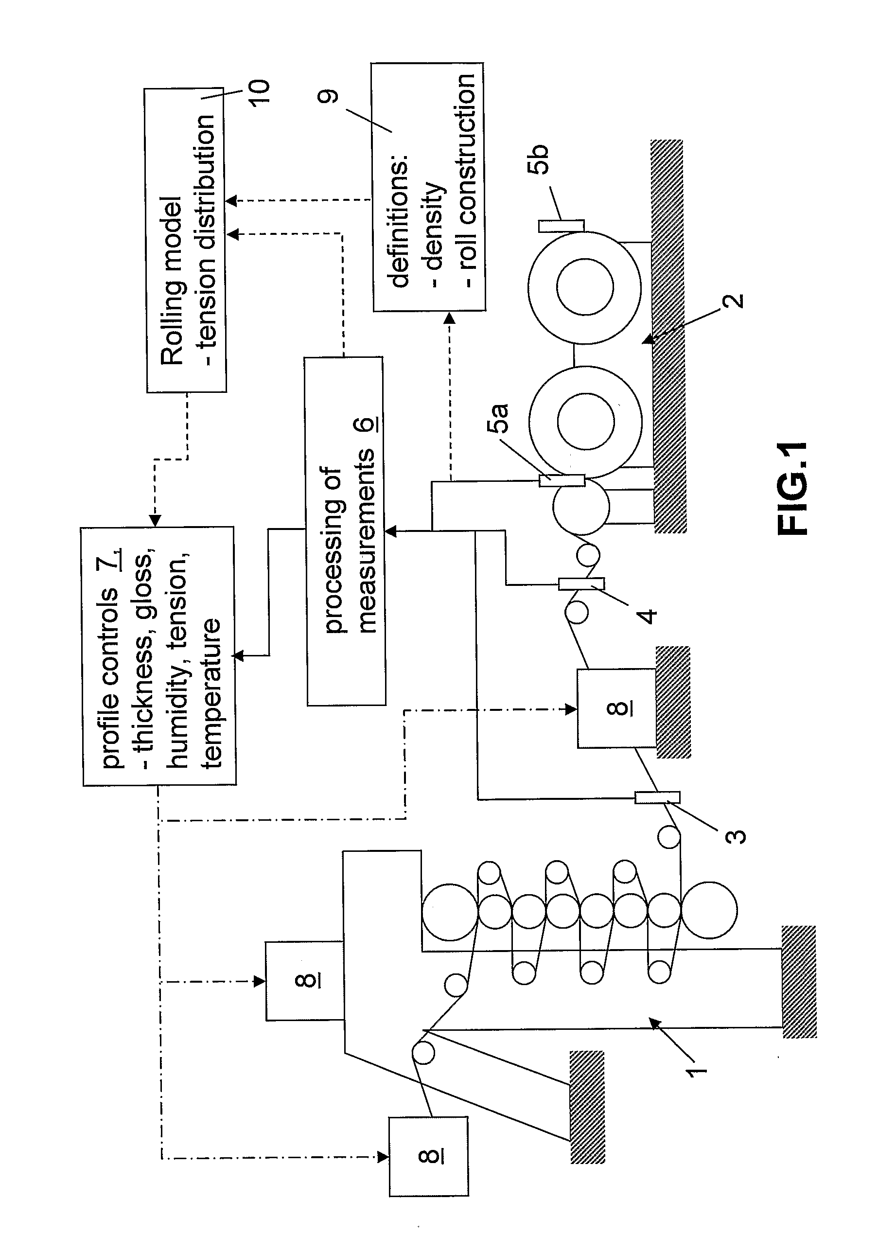
[0047] In the example of FIG. 1 profiling devices 8 which can be among others according to the invention: [0048] feeding tools of the fiber suspension arranged in the head box by adjusting the feeding of which in the CD-direction the smoothness of the fiber suspension can be directed in the CD-direction [0049] with the help of heat and pressure the material web is profiled by compression cylinders in the CD-direction and / or reel-ups for example in a pressing unit and in a drying unit and in a calender 1, [0050] in the CD-direction, the profiling drying cylinders affect profilings of the material web with the help of the heat or reel-ups for example in drying unit and calender [0051] in the CD-direction the humidifiers, evaporators and vapor boxes of the material web affect profiling of the material web for example with the help of the heat in a drying unit and calender unit [0052] the adjusting devices of the track tightness of the material web track, which can be located in differe...


PUM


Abstract

A method and a system to control a reeling profile of a material web reel (30), when, in the forming of a material web reel (30), a web is reeled around a reeling core and when in an adjustment of CD-directional profiles of the web reel, profiling devices (8) have been applied. For adjusting quality profiles and reeling profiles of the web, profiling devices are managed with the help of profile measurings of the roller nip and / or of the profile measurings of the reel (30), which are obtained from the reel-up (2). A measuring device (40) for a measuring of a CD-directional hardness profile of the fiber web reel includes a measuring head (43), which is connected with a loading means (41, 42), which loads the measuring head against the fiber web reel. The motion course of the measuring head is linear.

Description

CROSS REFERENCES TO RELATED APPLICATIONS [0001] This application is a U.S. national stage application of International App. No. PCT / FI2005 / 050265, filed Jul. 1, 2005, the disclosure of which is incorporated by reference herein, and claims priority on Finnish App. No. 20040919, filed Jul. 1, 2004, and Finnish App. No. 20055348, filed Jun. 27, 2005, the disclosures of which are incorporated by reference herein. STATEMENT AS TO RIGHTS TO INVENTIONS MADE UNDER FEDERALLY SPONSORED RESEARCH AND DEVELOPMENT [0002] Not applicable. BACKGROUND OF THE INVENTION [0003] The invention in question is connected with the forming of a machine reel or customer reel in the material web machine. The invention out in more detail is connected to the reeling method and to a system as for control a reeling profile a material web reel, like a machine reel or a customer reel. [0004] In the future the processing machines of different material webs are pointed to, for the sake of simplicity, with the qualifier ...

Claims


Application Information

Patent Timeline
IPC IPC(8): B65H18/26B65H23/00D21G9/00G01N29/06G01N3/42
CPCB65H18/26B65H2515/314B65H2701/1716D21G9/0045B65H23/195G01N29/07G01N33/34G01N2291/02827G01N2291/2696G01N9/24
Inventor MAENPAA, TAPIOTIITTA, JARILANNES, PETTERIVANNINEN, RAMIPITKANEN, TATUKETTUNEN, HEIKKIINNALA, MATTISHAKESPEARE, JOHNHEIKKILA, TONITYNKKYNEN, TOPIKOJO, TEPPOMAKINEN, RISTOTIILIKAINEN, MARKOKEMPPAINEN, MATTI M.
Owner VALMET TECHNOLOGIES INC
Learn More