


Quick Research
Generate reliable direction feasibility study reports for your R&D in just a few steps.

Technical Q&A
Discover and master advanced knowledge NOW. Basics, ideas, possibilities, all at once.

Find Solutions
As an expert in R&D theories, this can generate solutions to your technical problems instantly.

Evaluate Feasibility
Analyze your overall solution with one click, know your potential R&D risks in advance.

Monitor Landscape
Get weekly tech updates, stay abreast of the latest tech innovations and key insights.
Radiation imaging apparatus, driving method thereof and radiation imaging system
a technology of radiation imaging and driving method, which is applied in the direction of television system, instruments, applications, etc., can solve the problems of inability to improve the rate of continuous radiographing such as fluoroscopy, malfunction of image data deterioration during radiographing, and poor image quality, so as to reduce the image quality of radiation image data, without reducing image quality
- Summary
- Abstract
- Description
- Claims
- Application Information
AI Technical Summary
Benefits of technology
Problems solved by technology
Method used
Image

Examples
first embodiment
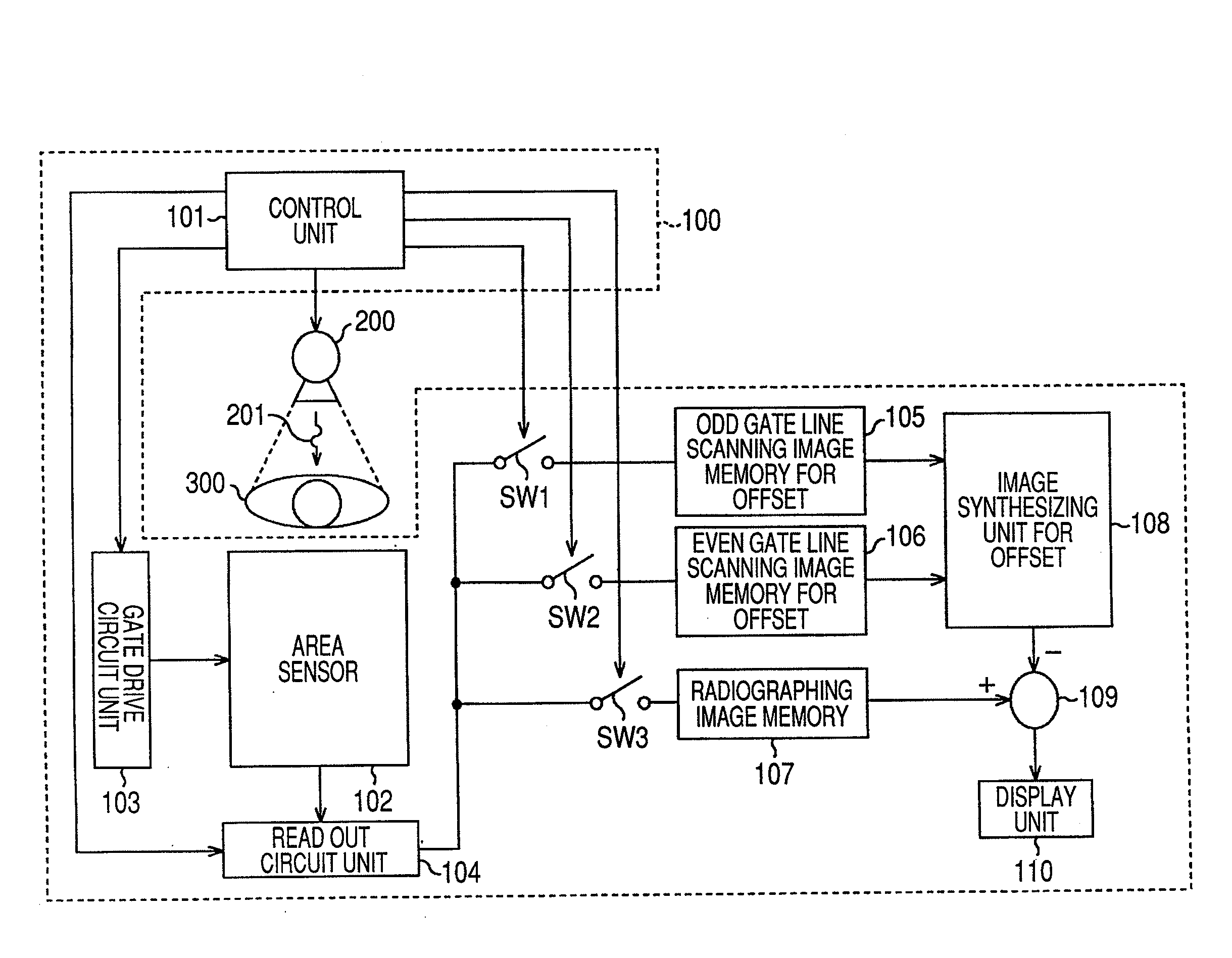
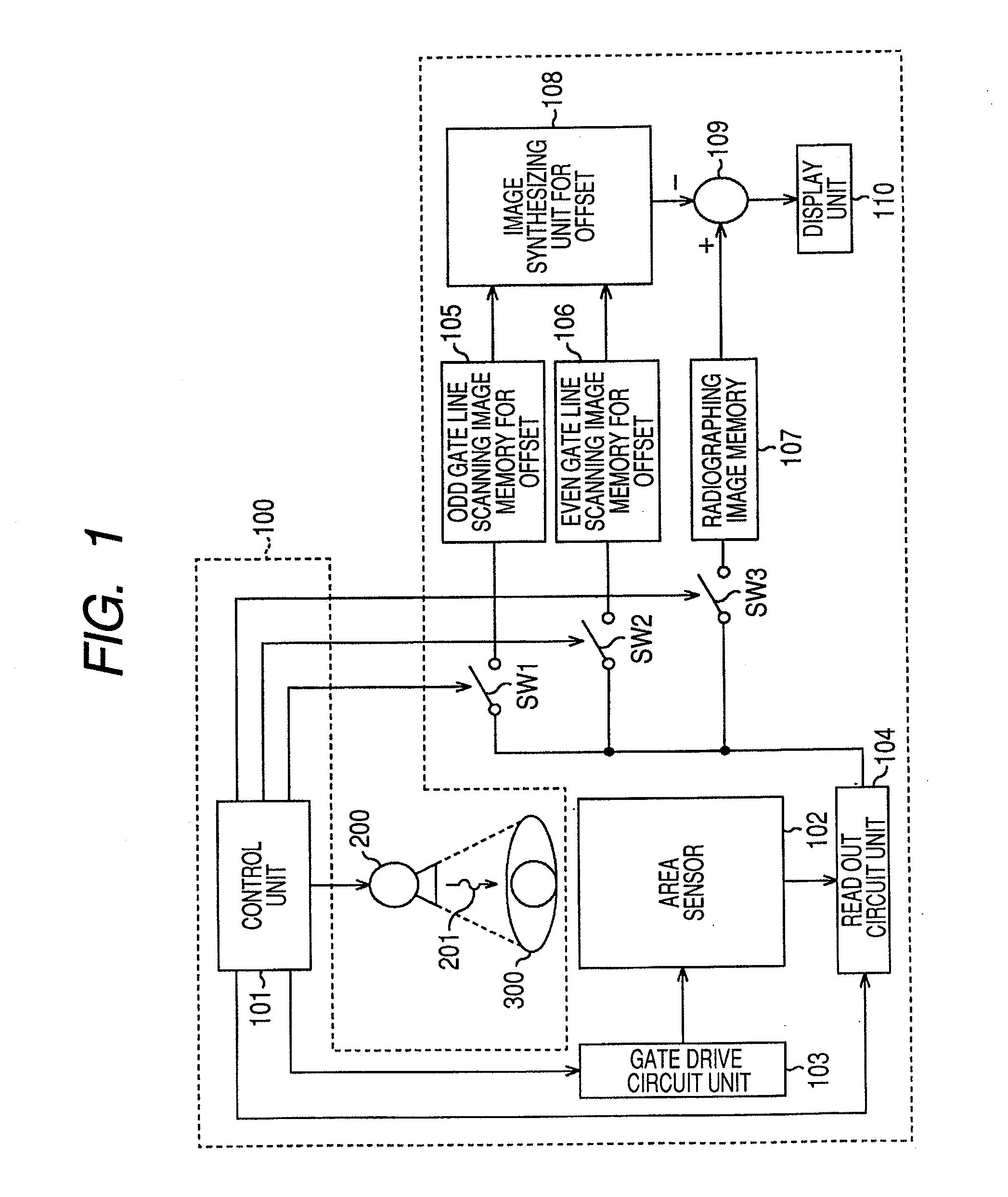
[0038]Hereinafter, by using FIGS. 1 to 6, a first embodiment of the present invention will be described in detail. FIG. 1 is a schematic block diagram of an X-ray imaging system (radiation imaging system) according to the first embodiment. The X-ray imaging system according to the present embodiment comprises an X-ray imaging apparatus (radiation imaging apparatus) 100 and an X-ray generator (radiation generator) 200.
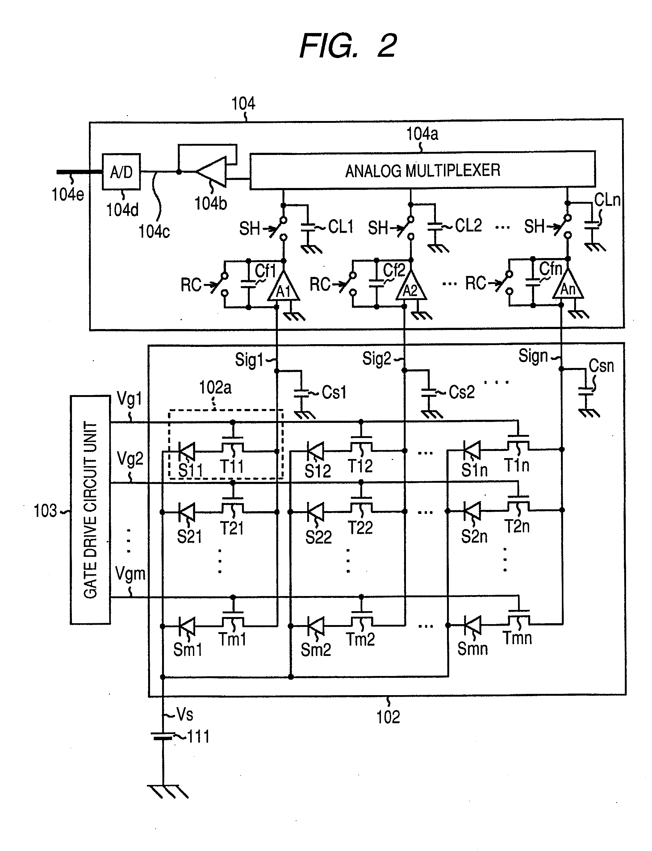
[0039]The X-ray imaging apparatus 100 of the present invention comprises a control unit 101, an area sensor 102, a driving circuit unit 103, a read out circuit unit 104, and a switch group comprising a first switch SW1, a second switch SW2, and a third switch SW3. Further, the X-ray imaging apparatus 100 comprises a first image memory 105 for offset, a second image memory 106 for offset, a radiation image memory 107, a processing unit 108 for synthesizing the images for offset correction, an arithmetic operation unit 109, and a display unit 110. In the present embodimen...
second embodiment
[0097]Hereinafter, a second embodiment of the present invention will be described by using FIG. 7. The second embodiment is an embodiment in which the importance is attached to a real-time image display by the display unit 110, and when the radiation image data and the image data for offset are renewed, an image display by the display unit 110 is immediately renewed. Incidentally, the schematic configuration of an X-ray imaging system (radiation imaging system) according to the second embodiment is given the following change only for the X-ray imaging system according to the first embodiment illustrated in FIG. 1.
[0098]That is, the second image memory 106 for offset illustrated in FIG. 1 is integrated into the first image memory 105 for offset and is made into an image memory for offset, and the second switch SW2 illustrated in FIG. 1 is deleted. In this case, in the image memory for offset, both of the image data of the first image data for offset correction and the second image da...
third embodiment
[0112]Hereinafter, a third embodiment of the present invention will be described by using FIGS. 8, 9A, and 9B. FIG. 8 is a schematic block diagram of an X-ray imaging system (radiation imaging system) according to the third embodiment. The X-ray imaging system according to the present embodiment comprises an X-ray imaging apparatus 130 and an X-ray generator 200.
[0113]The X-ray imaging apparatus 130 in the third embodiment, similarly to the X-ray imaging apparatus 100 in the first embodiment, comprises an area sensor 102, a driving circuit unit 103, a read out circuit unit 104, a radiation image memory 107, and a display unit 110.
[0114]The X-ray imaging apparatus 130 is provided with image memories 133 to 136 by a total four systems of A system to D system as memories to store the partial image data for offset correction every pixel group used at the time of the offset correction. Corresponding to these image memories 133 to 136 and the radiation image memory 107, a switch group com...
PUM
 Abstract
Description
Claims
Application Information
 - R&D Engineer
- R&D Manager
- IP Professional
- Industry Leading Data Capabilities
- Powerful AI technology
- Patent DNA Extraction
Browse by: Latest US Patents, China's latest patents, Technical Efficacy Thesaurus, Application Domain, Technology Topic, Popular Technical Reports.
© 2024 PatSnap. All rights reserved.Legal|Privacy policy|Modern Slavery Act Transparency Statement|Sitemap|About US| Contact US: help@patsnap.com