
Image display apparatus

Active Publication Date: 2011-09-29
JAPAN DISPLAY WEST
View PDF22 Cites 35 Cited by
  • Summary
  • Abstract
  • Description
  • Claims
  • Application Information

AI Technical Summary

Benefits of technology

[0011]Therefore, it is desirable to provide an image display apparatus which is less liable to cause a large reduction in an aperture ratio (high transmittance) and does not tend to suffer a problem such as color shifts, color mixtures, or interconnect reflections depending on the viewing angle.
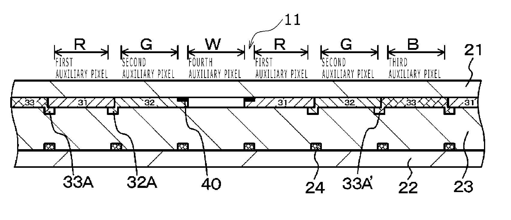
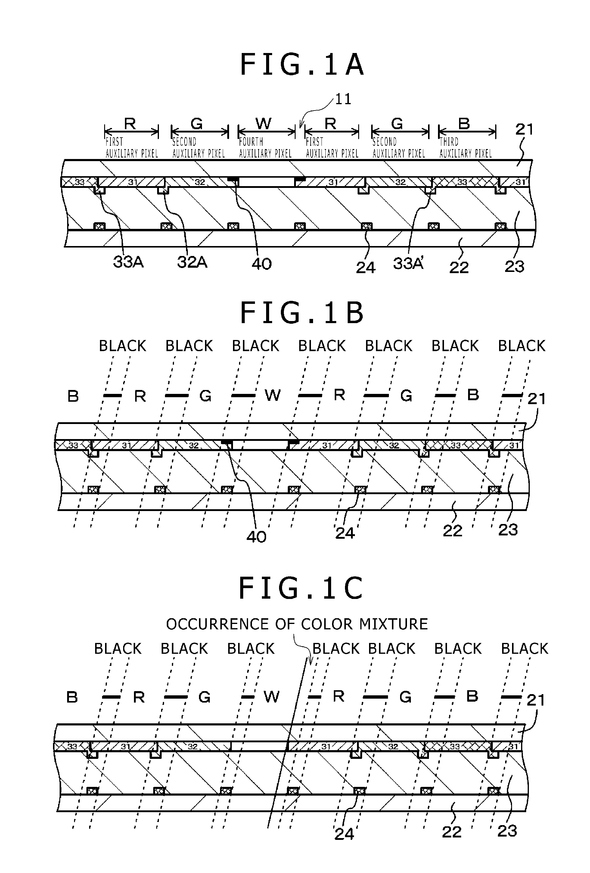
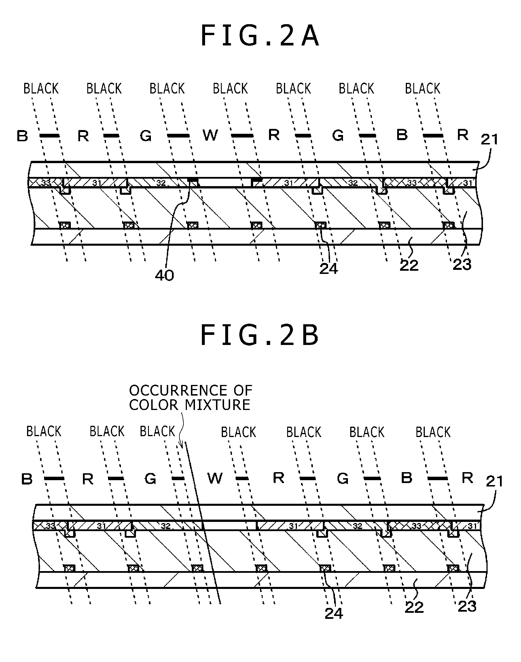
[0020]Since a light shielding region disposed at least partly around the peripheral edge of each of the fourth auxiliary pixels, the image display apparatus according to the present embodiments is prevented from suffering problems such as color shifts or color mixtures depending on the viewing angle, and is also prevented from large interconnect reflections around the fourth auxiliary pixels and hence from image quality degradations, etc. The light shielding region is also effective to prevent color shifts or color mixtures due to a misalignment error caused when the image display apparatus is assembled. The image display apparatus is capable of widening a dynamic range of luminance or reducing electric power consumption without impairing image quality.

Problems solved by technology

Furthermore, as illustrated in a conceptual fragmentary cross-sectional view shown in FIG. 3B, another problem is that there are large interconnect reflections around the fourth auxiliary pixel for emitting white light, resulting in an image quality degradation.
However, when external light indicated by the arrows “B” is applied to the color image display apparatus and hits interconnects 24, the external light is reflected by the interconnects 24 and will be emitted out of the color image display apparatus because there are no light shielding areas therefor, resulting in an image quality degradation.

Method used


Image

  • Image display apparatus
  • Image display apparatus
  • Image display apparatus

Examples


embodiment 1 (

2. Embodiment 1 (image display apparatus according to embodiments of the present invention, image display apparatus according to first mode of the present invention, and first configuration);

embodiment 2 (

3. Embodiment 2 (modification of Embodiment 1, image display apparatus according to first mode of the present invention, and second configuration);

embodiment 3 (

4. Embodiment 3 (modification of Embodiment 1, image display apparatus according to first mode of the present invention, and third configuration);


PUM


Abstract

An image display apparatus including an image display panel includes: a first color filter for passing light of a first primary and first auxiliary pixels for displaying the first primary; a second color filter for passing light of a second primary and second auxiliary pixels for displaying the second primary; a third color filter for passing light of a third primary and third auxiliary pixels for displaying the third primary; and fourth auxiliary pixels for displaying a fourth color; the first auxiliary pixels, the second auxiliary pixels, the third auxiliary pixels, and the fourth auxiliary pixels being arranged in a two-dimensional matrix, and a light shielding region disposed at least partly around the peripheral edge of each of the fourth auxiliary pixels.

Description

BACKGROUND OF THE INVENTION[0001]1. Field of the Invention[0002]The present invention relates to an image display apparatus.[0003]2. Description of the Related Art[0004]In recent years, image display apparatus such as color liquid crystal display apparatus or the like, for example, have been demanded to handle increased electric power consumption due to their higher performance capability. In particular, color liquid crystal display apparatus, for example, have backlights that consume more electric power because of their trends for higher definition, wider color reproduction range, and higher luminance. To solve the problem, attention has been drawn to a technology for constructing each display pixel of four auxiliary pixels which include a white display auxiliary pixel for displaying white color, for example, in addition to a red display auxiliary pixel for displaying red color, a green display auxiliary pixel for displaying green color, and a blue display auxiliary pixel for displ...

Claims


Application Information

Patent Timeline
IPC IPC(8): G02F1/1335
CPCG02F1/133514G02F1/133512G02F1/1335G02B5/003G02B5/201
Inventor MATSUI, YASUYUKIKABE, MASAAKI
Owner JAPAN DISPLAY WEST
Learn More