
Economical, scalable transceiver jitter test

a transceiver and jitter test technology, applied in the field of transceivers, can solve the problems of large and expensive test platforms, inability to fully account for the jitter of links, and inability to use traditional parallel bus interfaces

Active Publication Date: 2008-01-17
ALTERA CORP
View PDF8 Cites 35 Cited by
  • Summary
  • Abstract
  • Description
  • Claims
  • Application Information

AI Technical Summary

Benefits of technology

[0011]These and other features and advantages of the present invention will be presented in more detail in the following spe

Problems solved by technology

The protocols cover a spectrum of applications including communications, computer, industrial and storage applications, where there is a need to move large quantities of data between chips or across backplanes, but where traditional parallel bus interfaces can no longer be relied upon.
Although the serial loopback test is cost effective and can scale to match different transceiver data rates, it does not fully account for the jitter of the link.
Even though there are other conventional techniques available for testing a transceiver, they utilize large and expensive test platforms.

Method used


Image

  • Economical, scalable transceiver jitter test
  • Economical, scalable transceiver jitter test
  • Economical, scalable transceiver jitter test

Examples


Embodiment Construction

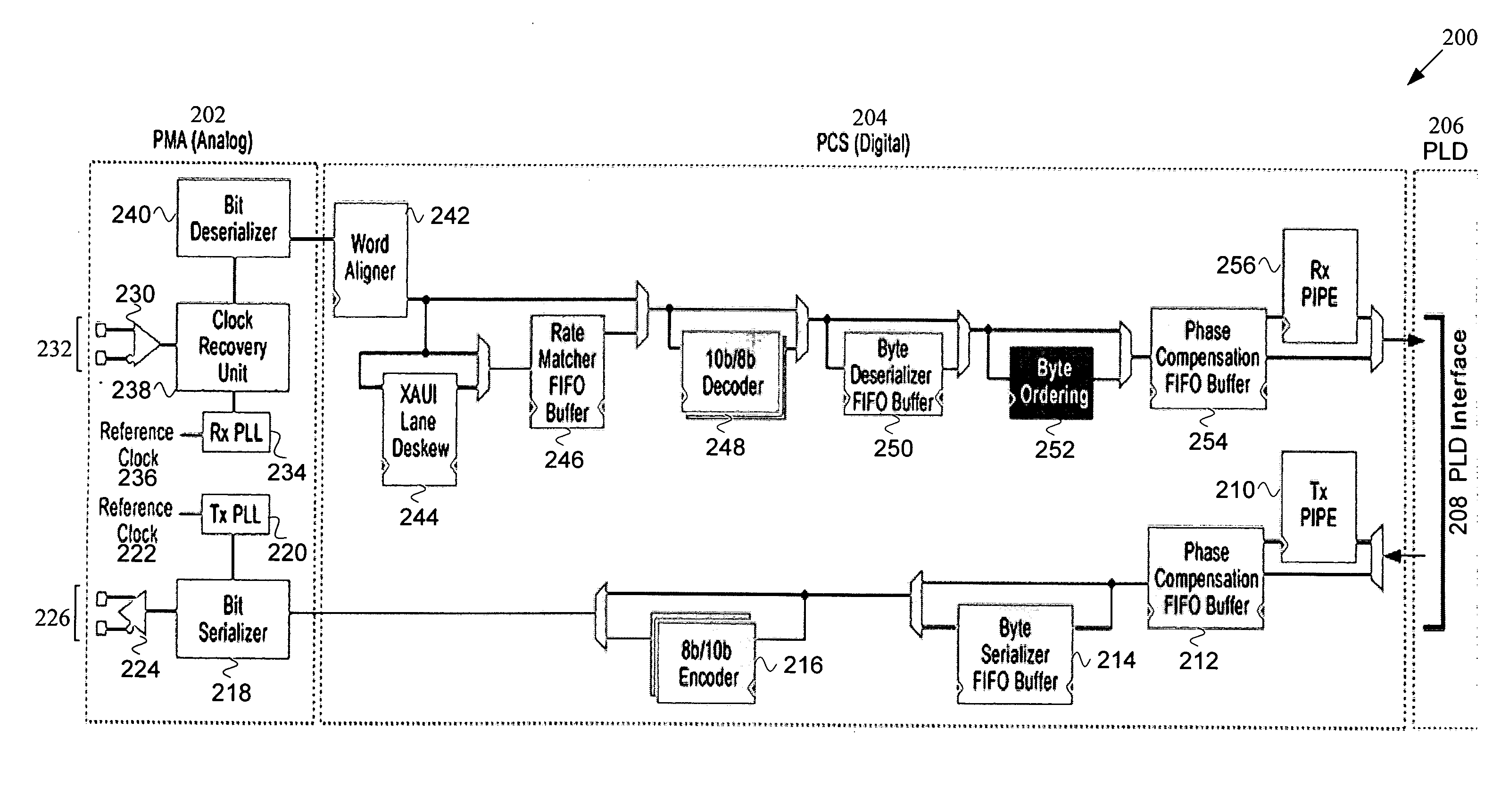
[0023]Reference will now be made in detail to some specific embodiments of the invention including the best modes contemplated by the inventors for carrying out the invention. Examples of these specific embodiments are illustrated in the accompanying drawings. While the invention is described in conjunction with these specific embodiments, it will be understood that it is not intended to limit the invention to the described embodiments. On the contrary, it is intended to cover alternatives, modifications, and equivalents as may be included within the spirit and scope of the invention as defined by the appended claims.

[0024]However, it should be noted that the techniques of the present invention can be applied to a variety of types of devices. In the following description, numerous specific details are set forth in order to provide a thorough understanding of the present invention. The present invention may be practiced without some or all of these specific details. In other instance...


PUM


Abstract

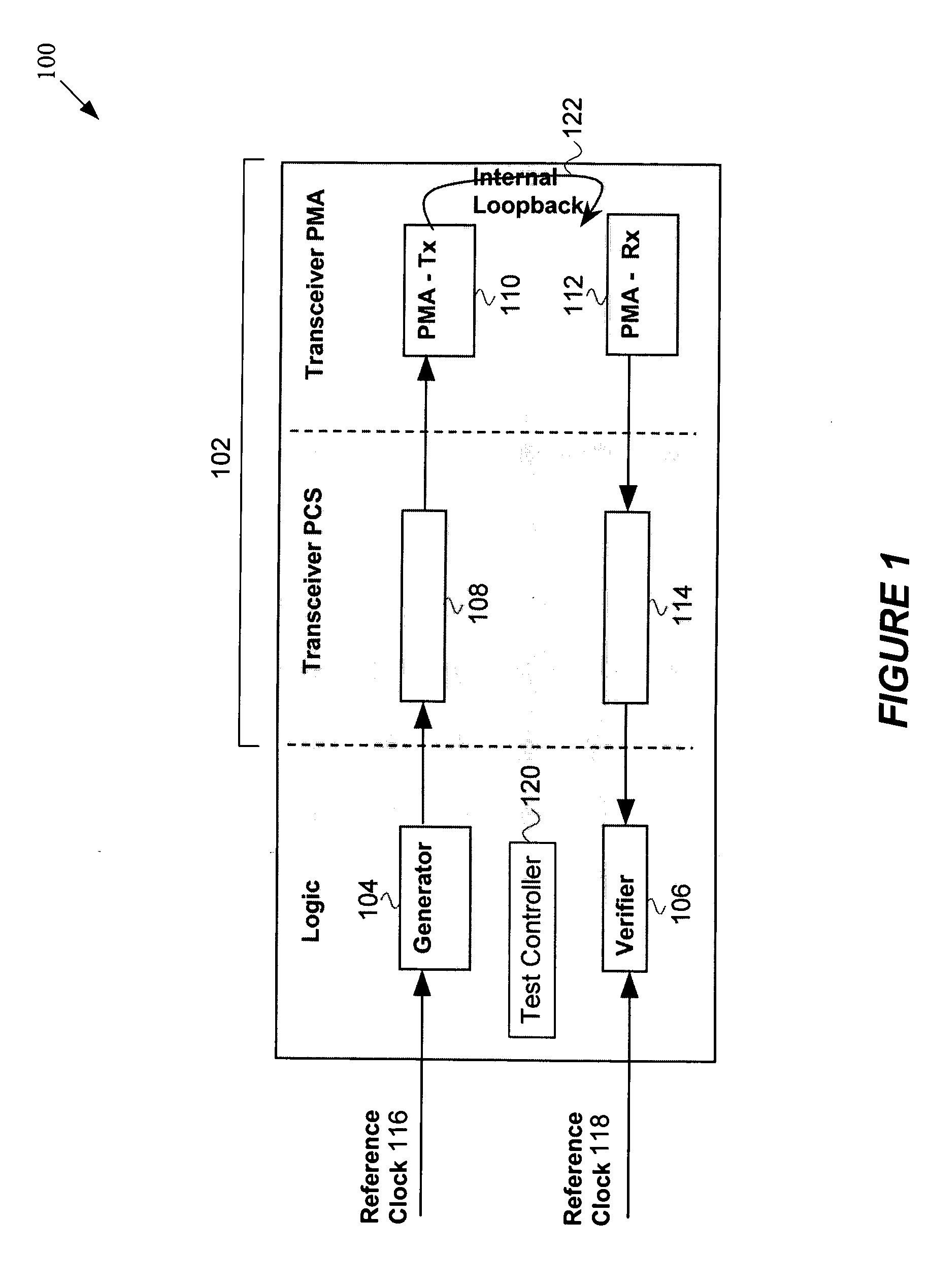
Any number of transceiver channels is tested for jitter generation / tolerance simultaneously. Tested channels use a serial loopback path to connect a transceiver transmit channel to a transceiver receiver channel. Both the transmitter and receiver PLLs are connected to a common reference clock. The reference clock is modulated with jitter at a frequency below the bandwidth of the transmitter PLL but above the bandwidth of the receiver PLL. The magnitude of eye closure (in an eye diagram), which is equivalent to the amplitude of the jitter, is used to filter out bad transceiver units.

Description

BACKGROUND OF THE INVENTION[0001]1. Field of the Invention[0002]The present invention relates to transceivers, and more particularly, to the testing of transceivers.[0003]2. Description of Related Art[0004]Many standards and protocols are now using a high-speed transceiver as part of their physical interface. The protocols cover a spectrum of applications including communications, computer, industrial and storage applications, where there is a need to move large quantities of data between chips or across backplanes, but where traditional parallel bus interfaces can no longer be relied upon.[0005]Conventional techniques for testing a transceiver include utilizing a serial loopback. For instance, Ducaroir et al., U.S. Pat. No. 6,331,999, describes a test method utilizing a serial loopback, which is hereby incorporated by reference for all purposes. Although the serial loopback test is cost effective and can scale to match different transceiver data rates, it does not fully account for...

Claims


Application Information

Patent Timeline
IPC IPC(8): H04L5/16H04B3/46
CPCH04B3/46H04L1/243H04L1/205
Inventor DAXER, KENNETH T.SHUMARAYEV, SERGEY
Owner ALTERA CORP
Learn More