Geometric end effector system

a technology of geometric end effectors and end effectors, which is applied in the field of robotics and manufacturing systems, can solve the problems of increasing the the labor cost of manually making such adjustments, and the high maintenance cost of the prior art use of multi-component robotic end effector assemblies, so as to reduce the production down time of the manufacturing line, easy to configure, and quick recovery

Active Publication Date: 2008-01-17
DELAWARE CAPITAL FORMATION INC
View PDF9 Cites 13 Cited by
  • Summary
  • Abstract
  • Description
  • Claims
  • Application Information

AI Technical Summary

Benefits of technology

[0016]One advantage of the present invention is that it may provide an improved modular geometric end effector system.
[0017]Still another advantage of the present invention is that it may reduce production down time of a manufacturing line.
[0018]Still another advantage of the present invention is that it may eliminate the need for a backup end effector system within a robotic cell on a manufacturing line.
[0019]Still another advantage of the present invention is that it may have predictable collision breakaway points for the components connected to the end effector system.
[0020]Still another advantage of the present invention is that it may provide an effector system that has modular components that are easily configurable and provide for quick recovery from crashes or other down time situations.
[0021]Still another advantage of the present invention is that it may provide a methodology of different platforms in robotic manufacturing lines.

Problems solved by technology

Furthermore, many of these prior art robotic cell systems having multiple components may be bumped, misaligned, or contaminated by environmental hazards in the manufacturing environment which requests that the line be shut down so that components could be completely removed and replaced or repaired such that the robotic cell could begin work once again in the manufacturing environment.
Therefore, the use of multi component robotic end effector assemblies in the prior art requires high maintenance and long down times to ensure exact positioning needed in the manufacturing environments found in many modern manufacturing settings.
Furthermore, many of these prior art systems require multiple adjustments to parts holding the components such as clamps, pins or the like on the end of the end effectors to properly align them, thus increasing the down time of the manufacturing line and labor costs required to make such adjustments manually thereto.

Method used


Image

  • Geometric end effector system
  • Geometric end effector system
  • Geometric end effector system

Examples


Embodiment Construction

)

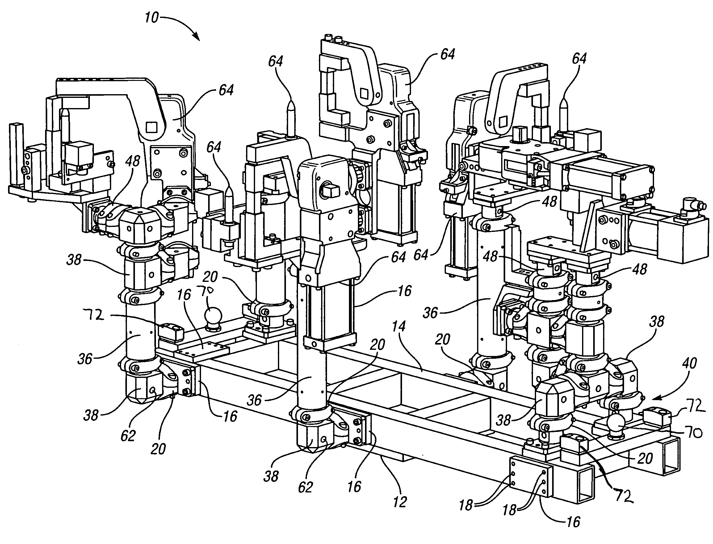
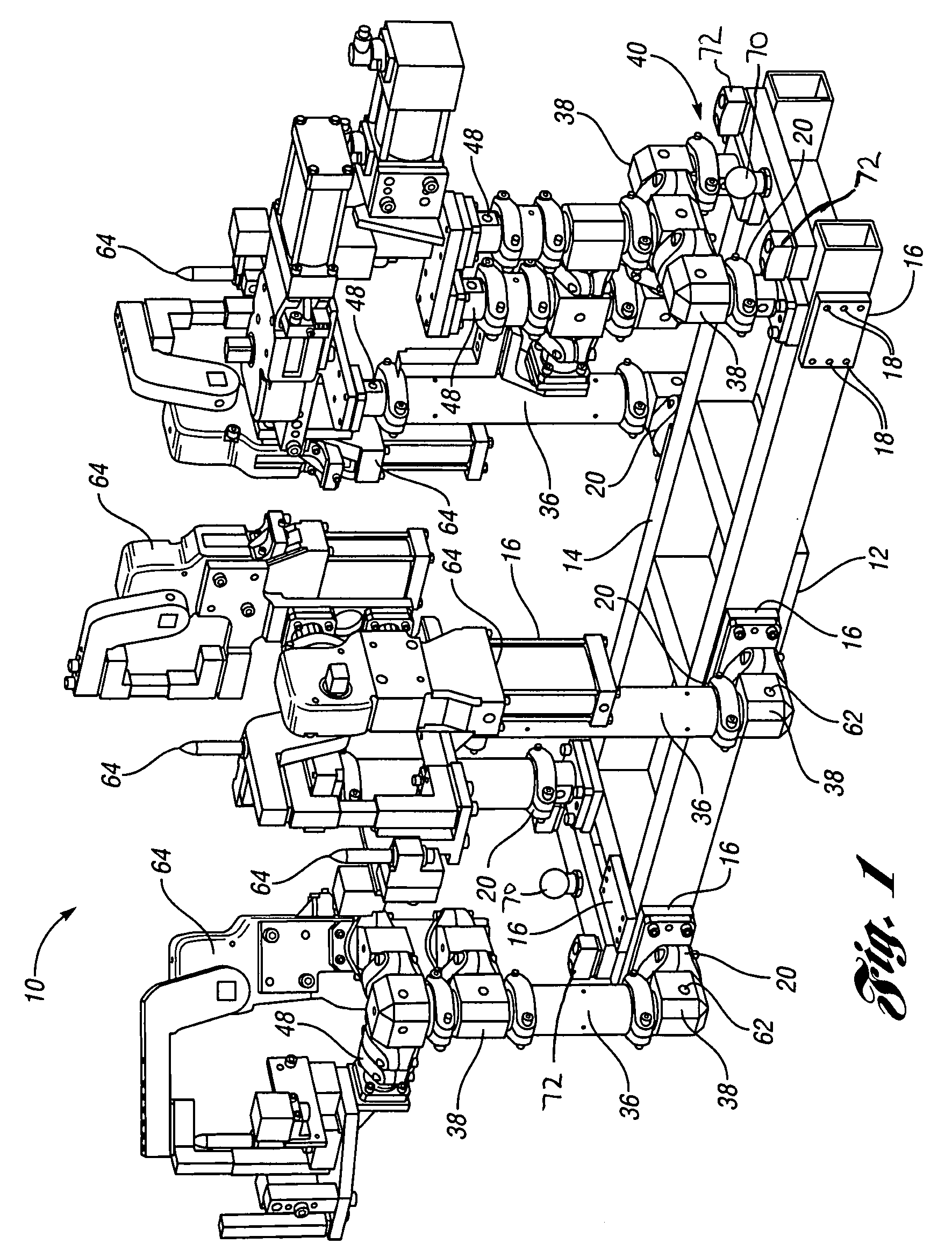
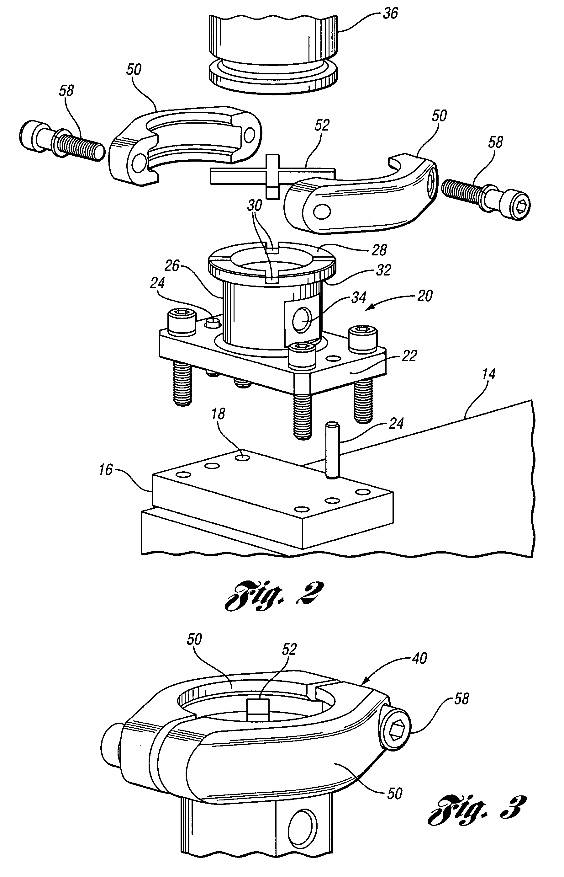
[0032]Referring to the drawings, a modular geometric end effector system 10 according to the present invention is shown. The geometric end effector system 10 is part of a robot that includes a robotic arm and a robotic wrist and / or other type of connection between a robot and the end effector system 10 that is used to work on a product or hold a product in the environment of the manufacturing robot. The geometric end effector system 10 is capable of being sized to connect to any known robot and it is also capable of being sized to pick up or hold any product that is being assembled or worked on in a robotic assembly line. In particular, the assembly may be used in an automobile manufacturing assembly line. It should be noted that the geometric end effector system 10 may be used to move a product or work piece being worked on from one position to another and then released. It should also be noted that the geometric end effector system 10 may be used to move a product and hold a prod...


PUM

PropertyMeasurementUnit
angleaaaaaaaaaa
total angleaaaaaaaaaa
thicknessaaaaaaaaaa

Abstract

A geometric end effector system for use on a robot. The system includes a platform and a frame secured to the platform. At least one base is arranged at a predetermined position on the frame. The system also has an anchor mount secured to the base and a component connected to an end of the anchor mount by a collar assembly. A key is arranged between the component and the anchor mount.

Description

BACKGROUND OF THE INVENTION[0001]1. Field of the Invention[0002]The present invention generally relates to robots and manufacturing systems and more particularly relates to a modular geometric end effector system for use with a robot.[0003]2. Description of the Related Art[0004]End effectors for use in assembly systems have been known in the prior art for many years. Generally, in many automated assembly systems, devices are used for holding and placing components and parts in a specified place so that a manufacturing, finishing or other intermediate step can be performed on the product being assembled or worked upon. These automated assembly systems generally employ many robots that minimize or eliminate the need for manual intervention, thus reducing the cost to the manufacturer of the labor and parts involved. The components used and made in such automated systems are typically made or moved by a robot via an arm or wrist all of which are well known methods in the prior art. Some...

Claims


Application Information

Patent Timeline
Patent Type & Authority Applications(United States)
IPC IPC(8): B25J9/18B23P19/10
CPCB25J19/065B25J15/0061Y10T29/5313Y10T29/53435Y10T74/20329Y10T29/5107Y10T29/5105Y10T483/18Y10T483/10
Inventor KNISS, JASON M.GOFF, MICHAEL J.BERENDT, JERRYMICALLEF, RON
Owner DELAWARE CAPITAL FORMATION INC
Why Eureka
Try Eureka