
Method and apparatus for separating particles

a technology of mechanical separator and separator, which is applied in the direction of magnetic separation, centrifuges, separation processes, etc., can solve the problems of re-entrainment of separated particles, structural filters have a capacity limit in terms of total allowable mass of captured particles, and inherent restrictions on the maximum concentration of particles, so as to reduce the size and energy requirements of mechanical separators. , the effect of reducing the energy inpu

Inactive Publication Date: 2008-01-10
WELLS PRODS GROUP
View PDF4 Cites 35 Cited by
  • Summary
  • Abstract
  • Description
  • Claims
  • Application Information

AI Technical Summary

Benefits of technology

[0014]Processing highly-loaded flows, separating nano-scale particulates from a gas stream and reducing the size and energy requirements of a mechanical separator are all desirable features of the separator. The separator effectively creates a differential velocity vector between the flow components, requires relatively lower energy input, and remains effective when high loading or nano-scale particles are present.

Problems solved by technology

Structural filters have a capacity limit in terms of total allowable mass of captured particles.
However, these devices have inherent restrictions on the maximum concentration of particles (mass per unit volume of gas) which they can efficiently process.
The configuration of these systems, and the turbulent flows within them, often results in re-entrainment of separated particles, especially under conditions of high loading or contained nano-particles.
In applications where either particles are very fine or the particle loading is quite high, or both, structural filters and conventional mechanical separators may not be economical or may fail altogether.
However, nano-sized particles are essentially the size of smoke particles, which are easily suspended in flowing gas.
Structural filters may be effective in removing nano-particles from air, but there are problems with pressure drop (energy loss), system volume and “harvesting” particles from the filter.
In desert operations, wind-borne sand damages engines, driven components and electrical devices.
As a result, structural filters are changed very frequently, with limited success at capturing nano-scale particles.
Mechanical filters exhibit two principal shortcomings—poor performance rejecting fine dust particles and excessive wear on fan blades and guide vanes from sand erosion.
Prior art separator designs have limited ability to process large mass flows having very high solids loading or that contain nano-scale particles.
Further, conventional mechanical separators may require large internal volumes or substantial energy to accelerate the gas-solid stream being treated.

Method used


Image

  • Method and apparatus for separating particles
  • Method and apparatus for separating particles
  • Method and apparatus for separating particles

Examples


Embodiment Construction

[0027]The new mechanical filtration separator is capable of collecting both fine, sub-micron particles and very high volumes of entrained solids. Further, it accomplishes these objectives with a relatively low energy input, less turbulent flow and using a more compact construction as compared to conventional mechanical separators.

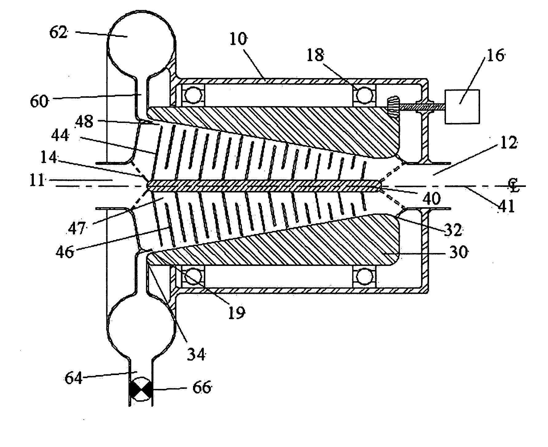
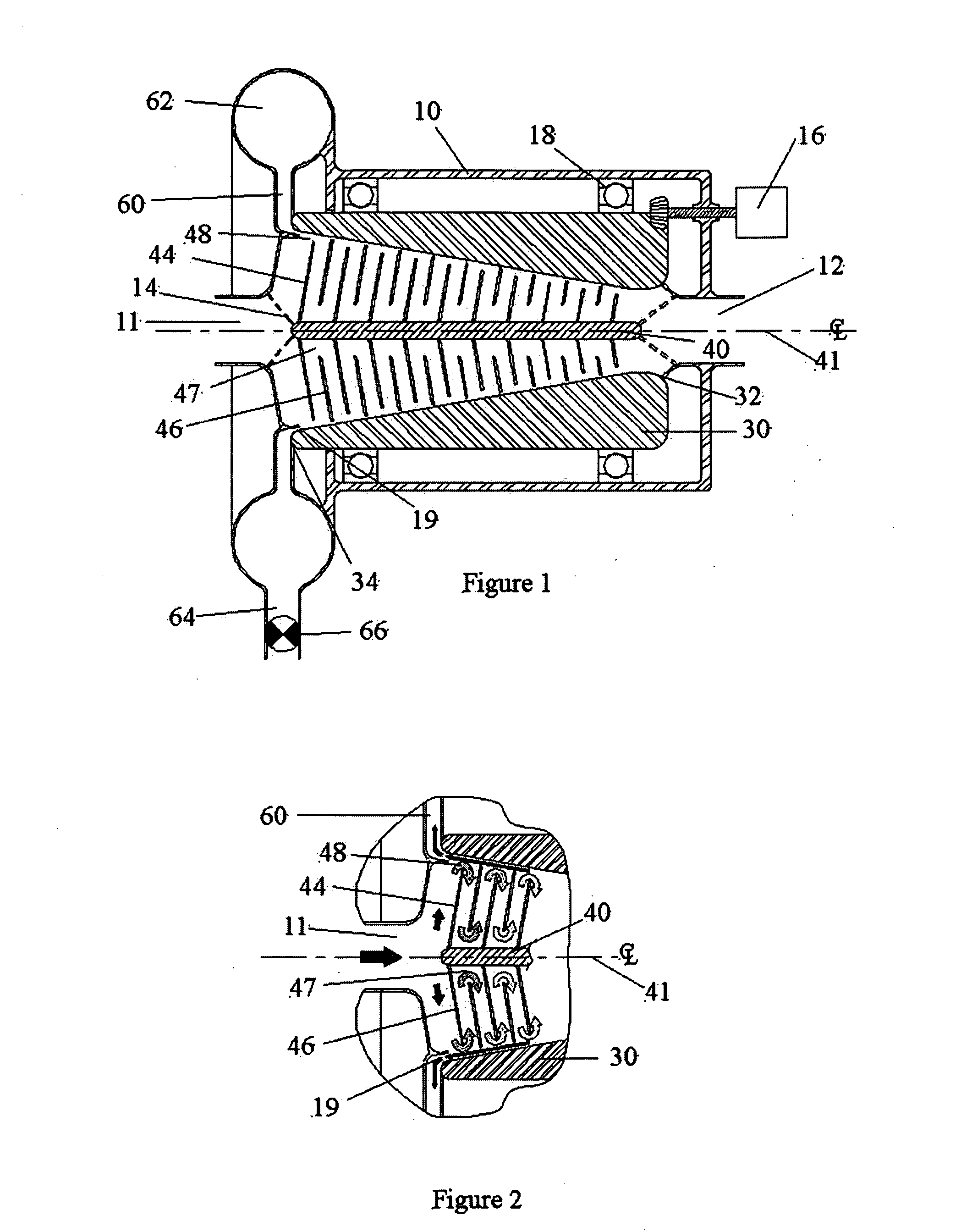
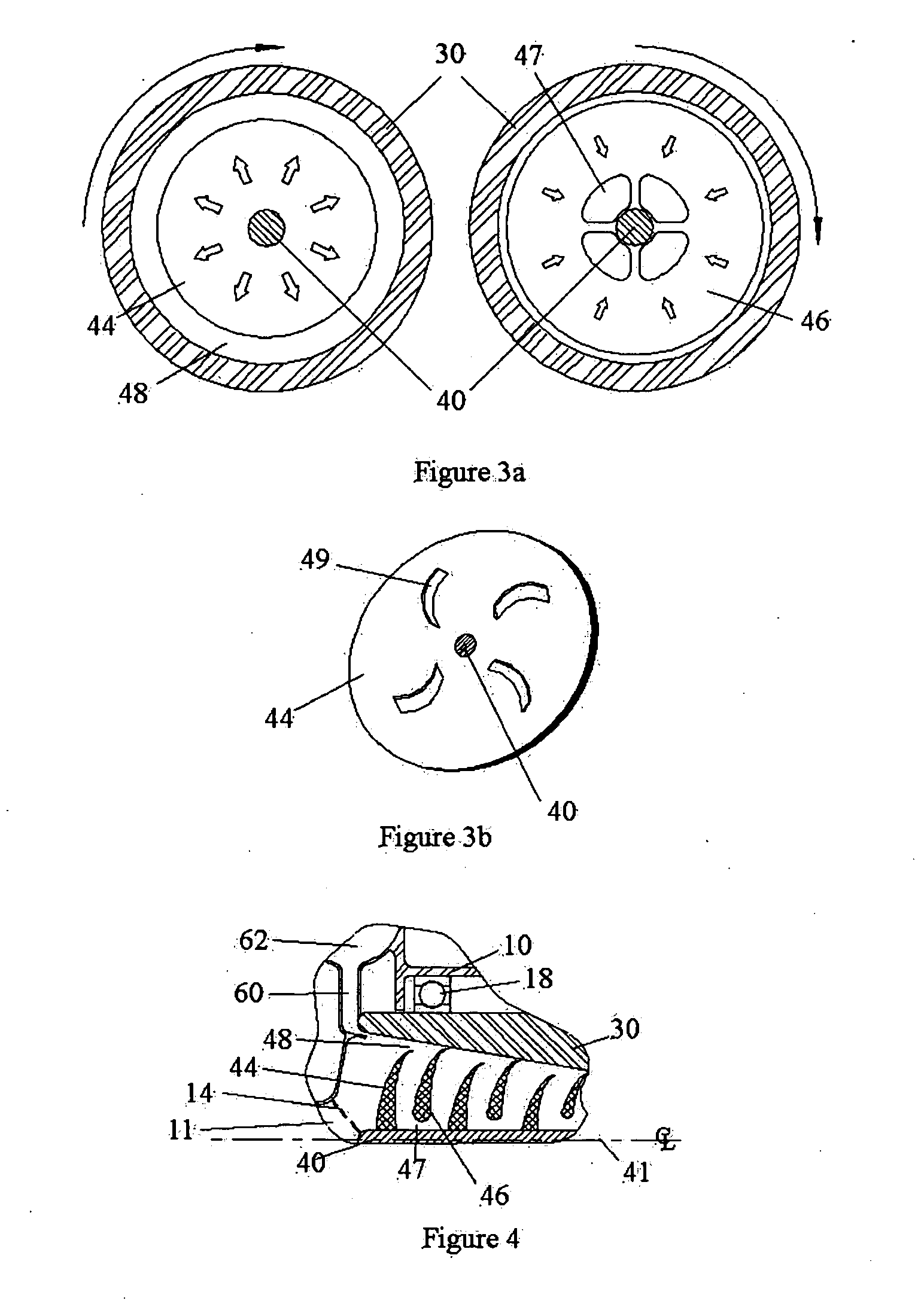
[0028]In a preferred embodiment, the separator is a reversing flow, rotating collector that uses a static interior vane assembly that reversibly directs fluid-solids flow in radial directions, first toward and then away from the inside wall of a rotating hollow collector. The non-rotating, axially coincident vane assembly may include a plurality of vanes. The vanes may be disk, conical, spherical or parabolic shaped, with each vane having a substantially outer edge. The vane assembly may be nested inside the rotating cone, such that gas-solids mixtures are repeatedly directed to reverse flow (from radially outward to radially inward) in the vicinity of the ...


PUM

PropertyMeasurementUnit
speedaaaaaaaaaa
velocityaaaaaaaaaa
diameteraaaaaaaaaa

Abstract

A method and apparatus for separating particles preferentially accelerates particles to a rotating collector, which then reliably conveys collected particles to a discharge with minimal re-entrainment of the particles in the fluid stream. The collector minimizes energy transfer to the fluid and maximizes separation under conditions of high particle loading, fine particle content, or both. The separator may be operated in any vertical, horizontal or oblique orientation, or within devices whose orientation varies over time.

Description

FIELD OF THE INVENTION[0001]The present invention relates to techniques for separating particles, such as solids or liquid droplets, from a gas. More particularly, the invention relates to more effectively processing gas streams containing a high mass content of particles and / or particles not easily separable, such as sub-micron or high aspect ratio particles.BACKGROUND OF THE INVENTION[0002]Two-phase (e.g., gas-solid, gas-liquid) flows are ubiquitous across a broad range of manufacturing, agricultural, medical and military applications. In many instances, the flow is intentional and controlled, as in pneumatic conveyors, pesticide applicators or drug delivery devices. In other applications, a gas contaminated with entrained particles / droplets must be refined, or particles / droplets entrained in a gas must be recovered for some further use. As used herein, a “particle” refers to both solid particles and liquid droplets.[0003]Across these applications, there is often a requirement to ...

Claims


Application Information

Patent Timeline
Patent Type & Authority Applications(United States)
IPC IPC(8): B04B1/20B04B3/04
CPCB01D45/14B04B5/10B04B5/08B04B1/08
Inventor KANE, JOHN E.HANCE, ROBERT L.
Owner WELLS PRODS GROUP
Learn More