
Insulated Jumper in Particular for Terminal Blocks of Switchboards

a technology of switchboards and jumpers, which is applied in the direction of electrically conductive connections, coupling device connections, electrical apparatus, etc., can solve the problems of high risk of contact with users, themselves and/or foreign bodies, and inability to electrically insulated, etc., and achieves the effect of easy and inexpensive production and assembly, and easy adaptability

Active Publication Date: 2008-01-10
MORSETTITALA
View PDF3 Cites 4 Cited by
  • Summary
  • Abstract
  • Description
  • Claims
  • Application Information

AI Technical Summary

Benefits of technology

[0009]In connection with this problem it is also required that this jumper should have small dimensions, be easy and inexpensive to produce and assemble and be able to be adapted easily at any user location using cutting means which are easy and inexpensive to provide.

Problems solved by technology

These known jumpers, although fulfilling their purpose, since they can be easily cut in the transverse direction in order to determine correct measurement in the longitudinal direction, have the drawback, however, that they cannot be electrically insulated with respect to the exterior, in particular at the time of use by a user; this results in a high risk of contact with the user him / herself and / or with foreign bodies and therefore injury both for the former, who may suffer an electric shock, and damage for the system which is short-circuited.
In order to solve the problem of insulation, jumpers are also known where the conductive strip is embedded in an insulating body; in this case also, however, there is the risk of drawbacks arising from the fact that cutting to size of the jumper is difficult owing to the double and different superimposed material, which requires complicated cutting operations using different tools respectively adapted to the type and thickness of material to be cut, making cutting practically impossible.
The technical problem which is posed, therefore, is to provide electrical connection jumpers, in particular for terminals of switchboards, which are able to be cut to size and ensure perfect insulation of the visible conducting parts so as to prevent them from coming into contact with the user and / or with foreign bodies, causing short-circuits of the system.

Method used


Image

  • Insulated Jumper in Particular for Terminal Blocks of Switchboards
  • Insulated Jumper in Particular for Terminal Blocks of Switchboards

Examples


Embodiment Construction

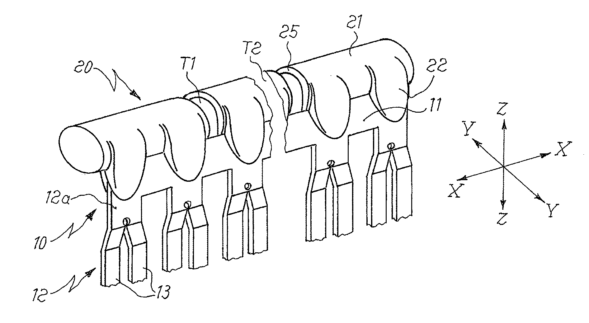
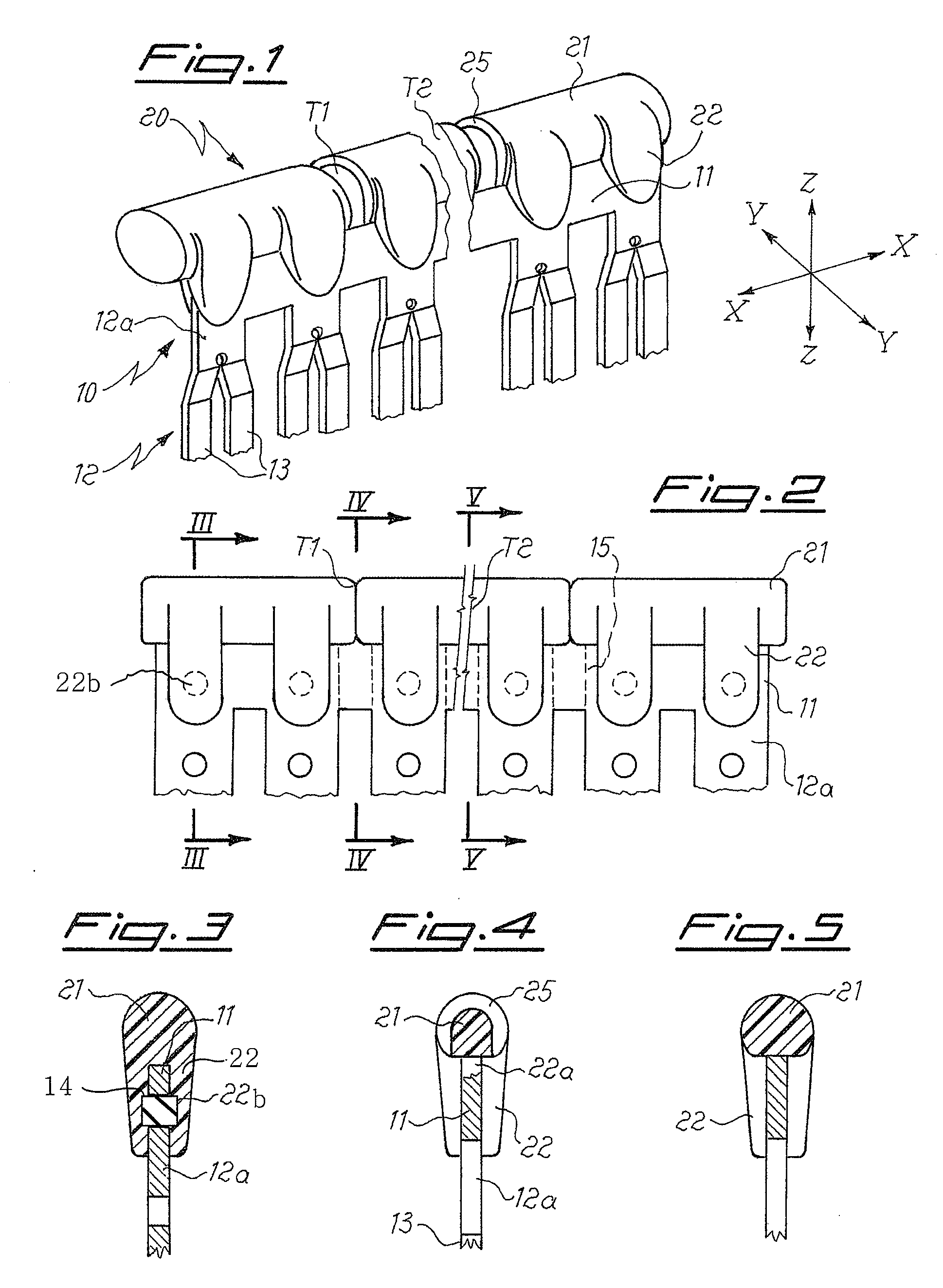
[0017]As shown in FIGS. 1 and 2 and assuming solely for the sake of convenience of the description and without a restrictive meaning, a set of three reference axes with a longitudinal direction X-X, transverse direction Y-Y and vertical direction Z-Z, respectively, the jumper for terminal blocks of switchboards according to the present invention comprises essentially: a conducting body 10 extending in the longitudinal direction X-X in the form of a thin strip 11 which has suitable dimensions for the electric load envisaged, and a plurality of connector elements 12 which extend in the transverse direction Y-Y from said strip 11 and are formed by a neck 12a which is extended by one or more (two in the example of the figure) flat pins 13 for connection to the terminal (not shown).

[0018]The conducting body 10 is integrally joined to an insulating body 20 comprising a substantially continuous, longitudinally extending gripping part 21 which, in the example shown in the figure, has a circ...


PUM


Abstract

Electrical connection jumper, in particular for terminal blocks of switchboards, comprising a conducting body extending in the longitudinal direction and a plurality of connector elements for electrical connection, which extend in the transverse direction from said conducting body, and an insulating body, integral with said conducting body, said insulating body comprising a longitudinally extending gripping part and pairs of lugs which extend therefrom in a substantially transverse direction and are able to contain partially said conducting body.

Description

BACKGROUND[0001]1. Technical Field of the Invention[0002]The present invention relates to an insulated jumper in particular for terminal blocks of switchboards and the like.[0003]2. Description of the Prior Art[0004]It is known in the technical sector relating to terminal blocks for switchboards that there exists the need to connect together two terminals arranged alongside each other on the board in order to form the required electric circuit.[0005]Jumpers made of conductive material and designed for this purpose are also known; said jumpers are formed by a conductive metal strip extending in a substantially longitudinal direction having, extending from it in a direction perpendicular to the above direction, flat pins formed in the manner of two resilient jaws able to form the part for engagement in the seat of the terminal block.[0006]These known jumpers, although fulfilling their purpose, since they can be easily cut in the transverse direction in order to determine correct measu...

Claims


Application Information

Patent Timeline
Patent Type & Authority Applications(United States)
IPC IPC(8): H01R4/02
CPCH01H71/082H01R9/2458H02B1/205H01R31/085H01R9/2675
Inventor PIZZI, GIORDANO
Owner MORSETTITALA
Learn More