Fitting for metal pipe and tubing

Inactive Publication Date: 2008-01-10
SWAGELOK CO
View PDF18 Cites 5 Cited by
  • Summary
  • Abstract
  • Description
  • Claims
  • Application Information

AI Technical Summary

Benefits of technology

[0005] The present invention is directed to improving the sealing capability of a fitting that uses a. fitting body and nut of certain commonly used dimensions as described above, while retaining the gripping capability. This is accomplished by providing a metal adaptor ring that seals effectively in a metal-to-metal manner against the body, while presenting a less shallow camming mouth for engagement by a ferrule. This combination of parts enables effective tube grip, fluid seal, and vibration protection.

Problems solved by technology

This 12° angle is, however, not conducive to establishing a good seal between the ferrule and the body.
Thus, the gripping and sealing functions are often at odds with each other in a fitting using such parts.
While fittings using elastomeric sealing elements generally seal effectively, they can have some drawbacks.
For example, temperature limitations may be placed on the fitting because of the presence of the elastomeric (non-metallic) element.
In addition, seal clipping or damage may occur during fitting make-up, or the seal element may fall out or be lost prior to fitting make-up.

Method used


Image

  • Fitting for metal pipe and tubing
  • Fitting for metal pipe and tubing
  • Fitting for metal pipe and tubing

Examples


Embodiment Construction

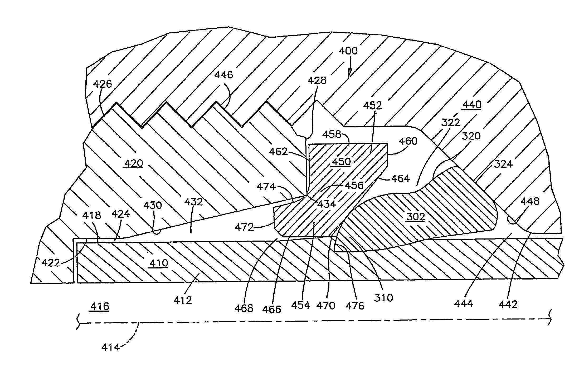
[0019] In many tube fittings, the nose of a ferrule is cammed inward toward and into the tube by a shallow (for example, 12° or 20°) camming surface or tapered surface on the fitting body. This angle is suitable for effecting tube gripping by the ferrule but is not optimal for also effecting a seal on the body by the ferrule. On the other hand, a steeper (for example, 45°) camming angle, can be better to effect a seal by the ferrule but can be less effective at producing the needed grip. The present invention as described below with reference to exemplary (but not limiting) embodiments addresses this issue.

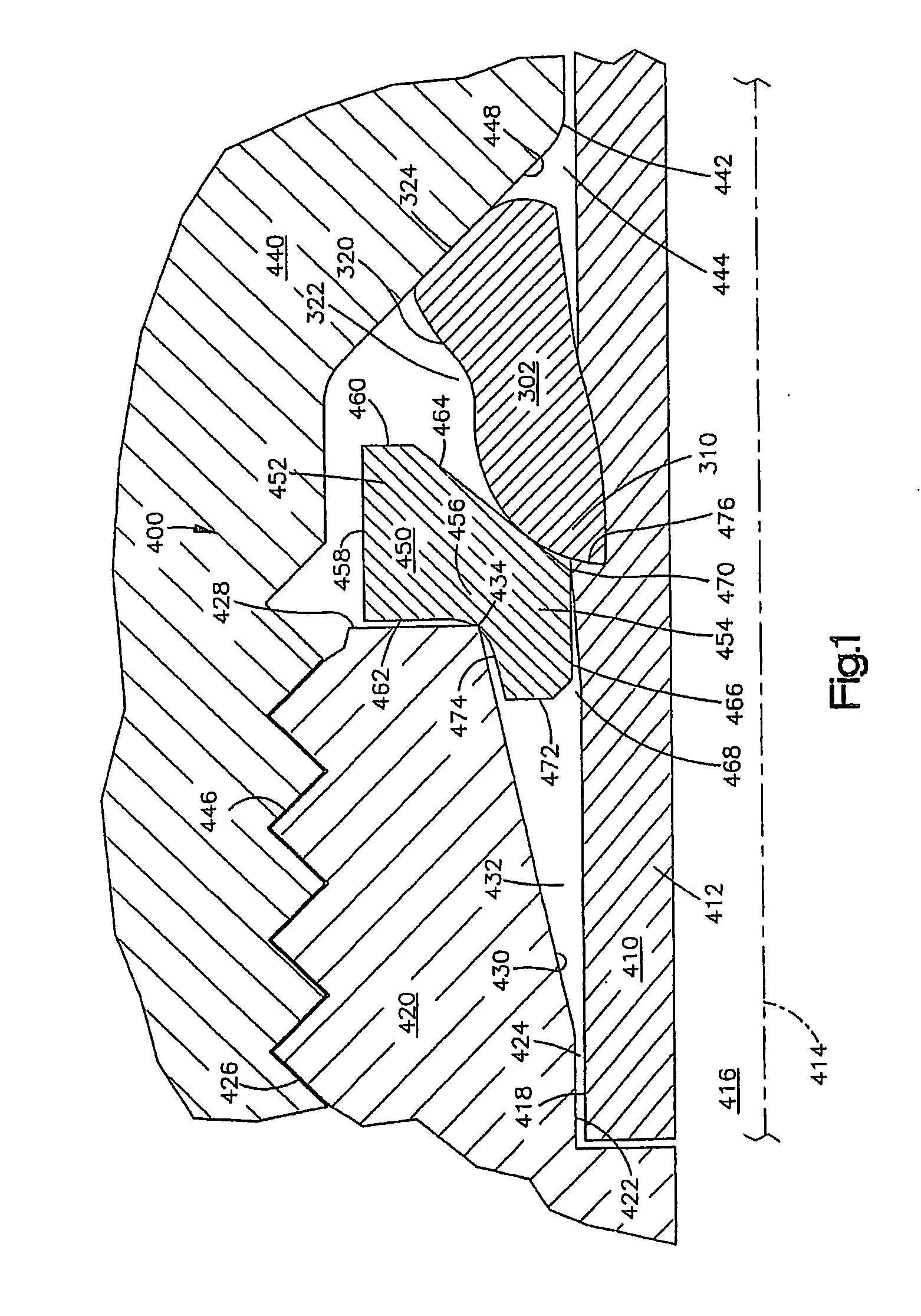
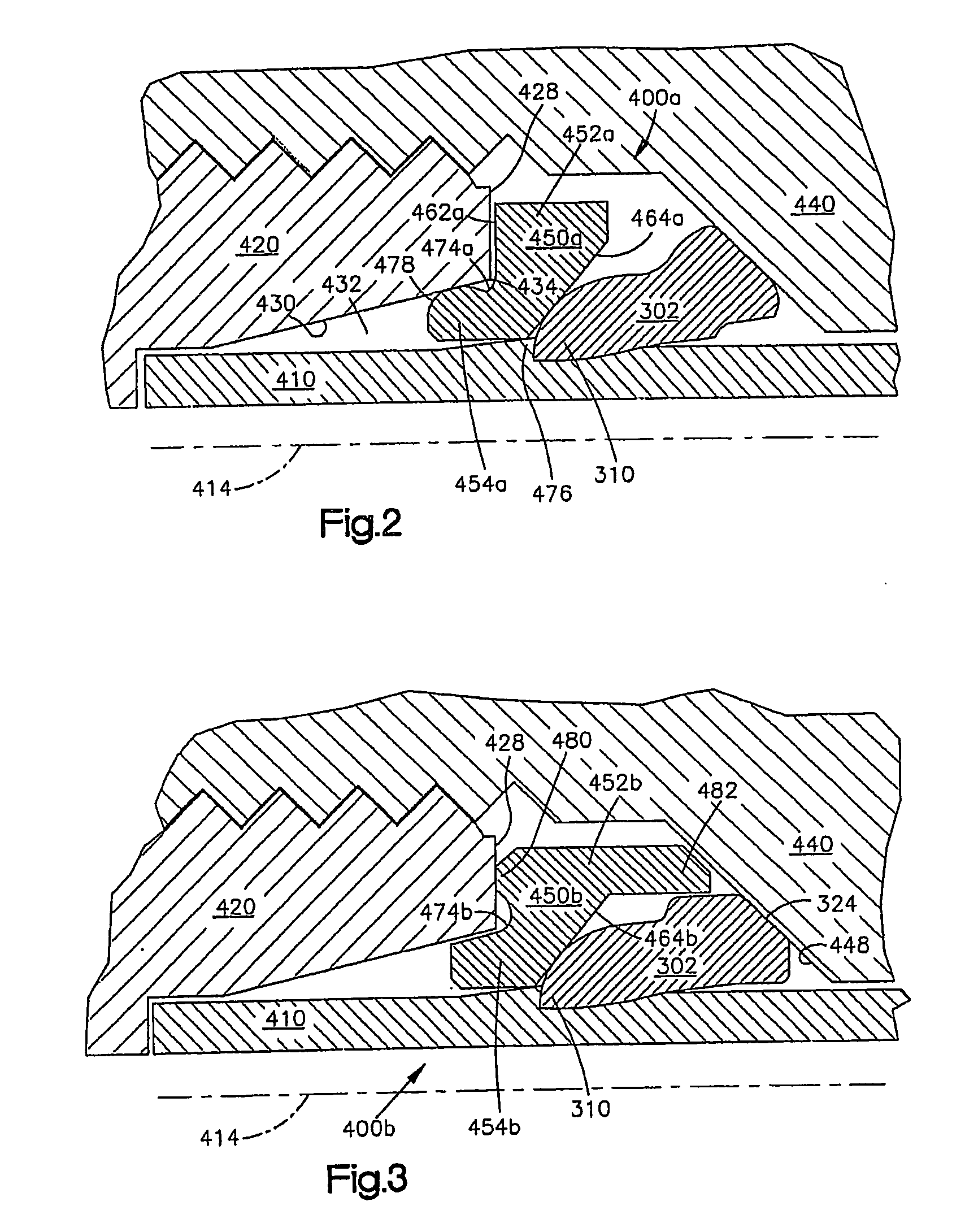
[0020]FIGS. 1-4 illustrate different tube fittings 400, 400a, 400b, and 400c in accordance with the invention. The various fittings 400-400c include differing features and combinations of features. A tube fitting in accordance with the present invention can include one or more of these features in different combinations.

[0021] Showing one representative embodiment, FIG. 1 illust...


PUM

PropertyMeasurementUnit
Angleaaaaaaaaaa
Angleaaaaaaaaaa
Angleaaaaaaaaaa

Abstract

A fitting arrangement with an adapter for use in a fitting that uses a fitting body and nut of certain commonly used dimensions as described above, while retaining the gripping capability. The adapter is a ring that seals effectively against the body, while presenting a less shallow camming mouth for engagement by a ferrule. This combination of parts enables effective tube grip, fluid seal, and vibration protection.

Description

[0001] This application is a continuation in part of U.S. patent application Ser. No. 10 / 559,316 filed Dec. 5, 2005, and claims the benefit of PCT Application No. PCT / US2004 / 036677 filed Nov. 3, 2004, which claims the filing date of U.S. Provisional Application No. 60 / 481,593 filed Nov. 3, 2003, the entire disclosures of which are incorporated herein by reference.TECHNICAL FIELD OF THE INVENTION [0002] The subject invention is generally directed to the art of fittings for pipe and tube. More particularly, the invention is directed to flareless fittings that include a fitting body with a shallow angle tapered surface and a tube gripping device, such as a ferrule or tube gripping ring. [0003] This application incorporates by reference the entire disclosure of International patent application no. PCT / US02 / 03430 filed on Feb. 6, 2002 for TUBE FITTING FOR STAINLESS STEEL TUBING. BACKGROUND OF THE INVENTION [0004] Some known tube fittings employ parts that are at least partially standardi...

Claims


Application Information

Patent Timeline
IPC IPC(8): F16L47/00
CPCF16L19/103F16L19/086F16L37/05F16L19/08
Inventor WILLIAMS, PETERMEDVICK, RICHARDRUBINSKI, JEFFREYARSTEIN, DALEBENNETT, MARK
Owner SWAGELOK CO
Why Eureka
Try Eureka